


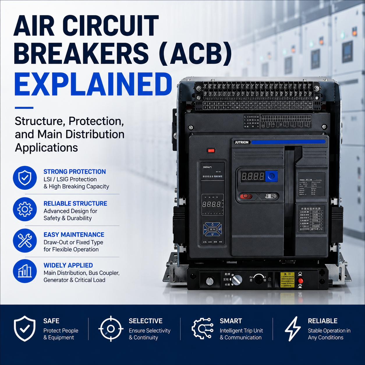
Air Circuit Breakers (ACB) Explained: Structure, Protection, and Main Distribution Applications
In a low-voltage power distribution network, molded case circuit breakers (MCCBs) installed on branch circuits are responsible for overload and short-circuit protection in their respective circuits. In contrast, the air circuit breaker (ACB), also commonly referred to in the industry as a universal circuit breaker, installed at the incoming side of the main distribution board (MDB), plays a core role in main incoming control, system protection coordination, and high-current main power distribution management.
Many junior engineers or purchasers without an electrical background often simply understand an ACB as “a larger MCCB with a higher current rating.” However, in real industrial sites and large commercial buildings, the value of the main incoming breaker is never limited to a higher rated current. Its real importance lies in whether it can provide stronger short-time withstand capability, more complete protection setting logic, and reliable support for system selectivity and power supply continuity when a fault occurs.
The reason ACBs have long been used in main incoming circuits and high-current main distribution circuits is not simply because they are larger in size. More importantly, ACBs offer system-level advantages that are clearly different from ordinary low-voltage circuit breakers in terms of structural maintainability, short-time withstand current (Icw), accessory expandability, and intelligent protection functions.
What Is an Air Circuit Breaker (ACB)?
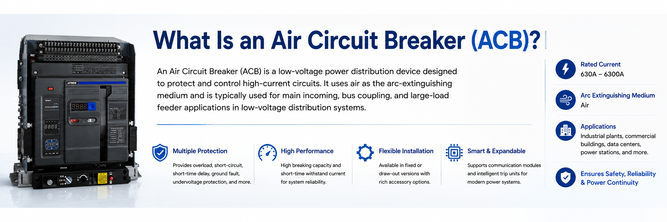
Core features of a modern Air Circuit Breaker (ACB). Its high breaking capacity and flexible draw-out design make it the undisputed heart of Main Distribution Boards (MDBs).
An ACB, or Air Circuit Breaker, is a key protection and control device used in low-voltage power distribution systems. It is especially suitable for main incoming feeders, bus couplers, and high-current main distribution circuits. It uses air as the arc-extinguishing medium and commonly has rated current ranges from 630A to 6300A. Unlike ordinary branch circuit breakers, an ACB is designed with a stronger focus on system-level protection coordination, short-time withstand capability, and power supply continuity.
For low-voltage circuit breakers, IEC 60947-2 is one of the main international reference standards used to define performance requirements such as breaking capacity, short-time withstand capability, and protection coordination.
Key Features and Common Parameters of an ACB
The ACB has a wide rated current range, commonly covering 630A to 6300A, meeting the load-carrying requirements of large main distribution circuits.
It has strong short-circuit breaking capacity, with ultimate short-circuit breaking capacity reaching 50–150kA, allowing it to quickly interrupt short-circuit fault currents.
It provides multiple adjustable protection functions, including long-time overload protection, short-time delay short-circuit protection, instantaneous short-circuit protection, and undervoltage protection. Protection parameters can be adjusted on site.
It supports multiple operation modes, including manual opening and closing, motorized spring-charging operation, and remote automatic control through PLC connection.
The draw-out structure provides connected, test, and isolated positions, making inspection and replacement more convenient without removing the switchboard.
It is commonly suitable for 400V and 690V low-voltage AC distribution systems.
Main Components of an Air Circuit Breaker (ACB)
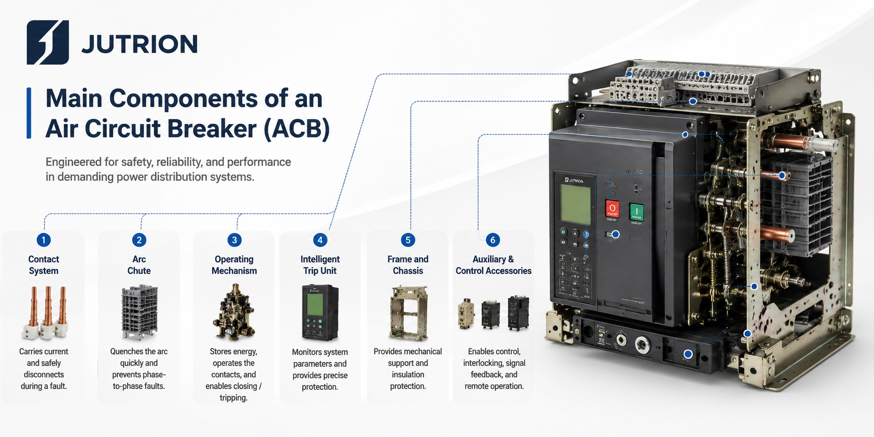
The modular anatomy of a modern ACB. Unlike sealed MCCBs, the open-frame chassis allows engineers to independently inspect, maintain, or replace core components—such as the arc chutes and operating mechanism—drastically reducing maintenance downtime in critical facilities.
The structure of an ACB is designed around three core objectives: reliable current carrying, fast fault interruption, and stable protection control. It is usually composed of the following key parts:
1. Contact System
- It includes the main contacts and arcing contacts, which are the core components responsible for carrying and interrupting current.
- The main contacts carry the rated current during long-term operation, while the arcing contacts are designed to withstand arc erosion first and protect the main contacts.
- A multi-stage contact structure is often used together with a fast spring mechanism to achieve arc-free main contact separation and long electrical life.
2. Arc Chute
- The arc chute uses air as the arc-extinguishing medium, and its internal structure usually contains metal splitter plates or a labyrinth-type arc chamber.
- After the arc enters the arc chute, it is split, cooled, stretched, and quickly extinguished, helping to prevent phase-to-phase short circuits.
- It is a key component that determines the ultimate breaking capacity of an ACB.
3. Operating Mechanism
- It includes the energy storage mechanism, transmission mechanism, and trip mechanism.
- It supports manual operation, motorized spring charging / closing, and can realize both local and remote control.
- A four-bar or five-bar linkage mechanical structure is commonly used to ensure fast, stable, and smooth opening and closing actions.
4. Intelligent Trip Unit / Protection Unit
- It is the “brain” of the ACB and integrates multiple protection functions, such as long-time overload protection, short-time delay short-circuit protection, instantaneous short-circuit protection, and undervoltage / loss-of-voltage protection.
- It supports the collection of multiple parameters such as current, voltage, and temperature. The protection curve can be adjusted locally or remotely.
- Some models are equipped with communication interfaces and can be connected to PLCs or power monitoring systems to realize remote communication, remote measurement, and remote control.
5. Frame and Chassis
- It provides mechanical support and insulation protection. Draw-out structures are widely used in mainstream ACB designs.
- It includes three positions: connected position, test position, and isolated position, making online inspection, maintenance, and breaker replacement more convenient.
- Internal insulation barriers and phase-to-phase insulation components are integrated to prevent internal short circuits.
6. Auxiliary and Control Accessories
- Common accessories include auxiliary contacts, shunt releases, undervoltage releases, motor operating mechanisms, energy storage motors, and other control components.
- These accessories enable signal feedback, interlocking control, automatic opening and closing, and compatibility with power distribution automation systems.
How Does an Air Circuit Breaker Work?
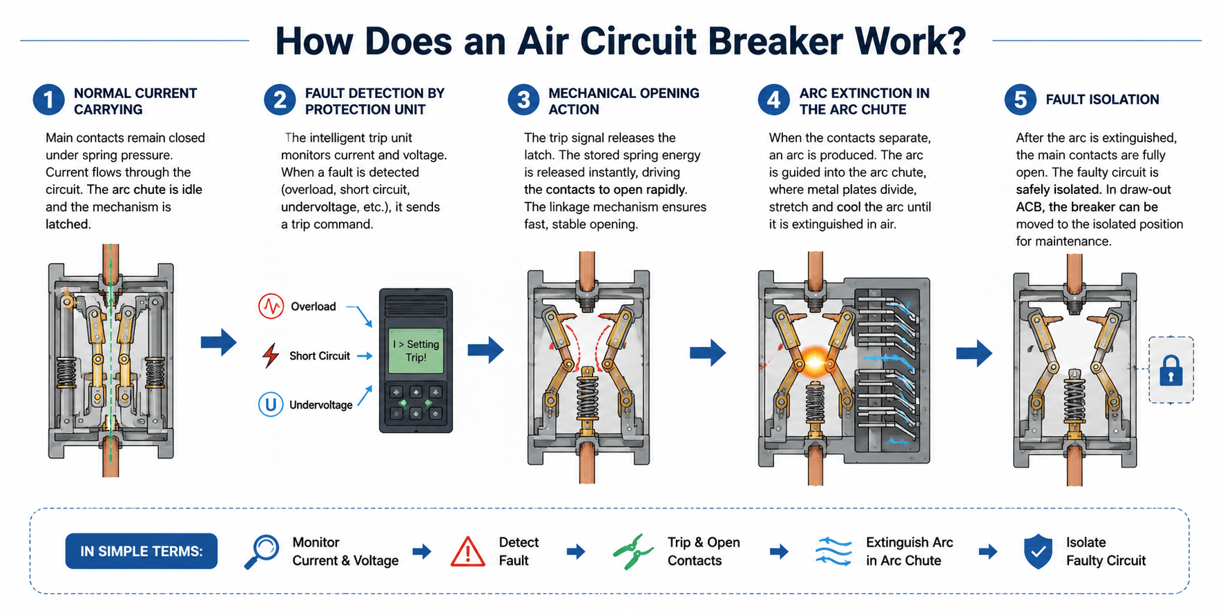
How an Air Circuit Breaker (ACB) works during fault interruption
In simple terms, an ACB works like an “intelligent main safety switch” in a low-voltage main distribution system. During normal operation, it carries high current continuously. When faults such as overload, short circuit, undervoltage, or loss of voltage occur, it can quickly and reliably disconnect the circuit to prevent the fault from spreading.
1. Normal Current Carrying
During normal operation, the main contacts remain tightly closed under spring pressure, allowing current to flow through the contact system and conductor path. At this stage, the arc chute does not operate. The operating mechanism remains in the charged and latched position, keeping the breaker closed.
2. Fault Detection by the Protection Unit
The intelligent trip unit continuously monitors current and voltage signals. When an abnormal condition is detected, it decides whether the breaker should trip according to the preset protection settings.
For overload faults, the current exceeds the preset value, and the trip unit sends a trip command according to the long-time delay protection curve.
For short-circuit faults, the current rises sharply, and the trip unit responds through short-time delay or instantaneous protection.
For undervoltage or loss-of-voltage conditions, the undervoltage release can trigger the breaker to open.
3. Mechanical Opening Action
After the trip signal is issued, the latch inside the operating mechanism is released. The stored spring energy is discharged instantly, driving the contact system to open rapidly. A four-bar or five-bar linkage mechanism helps ensure fast, stable, and smooth opening action.
4. Arc Extinction in the Arc Chute
When the contacts separate under load or fault current, a high-temperature arc is generated between the contacts. This arc is guided into the arc chute, where metal splitter plates divide, stretch, and cool the arc. The arc is then extinguished in air, preventing phase-to-phase faults or equipment damage.
5. Fault Isolation
After the opening action is completed, the main contacts are fully separated and the arc is extinguished. The faulty circuit is safely isolated. In some draw-out ACB designs, the breaker can also be moved to the isolated position, providing physical separation for inspection and maintenance.
One-sentence summary:
An ACB safely interrupts a faulty circuit through the complete process of protection unit fault detection → rapid opening by the operating mechanism → arc extinction in the arc chute, helping protect the distribution system and electrical equipment.
ACB Protection Functions: Understanding LSI and LSIG Protection
The protection functions of an ACB are like an “intelligent safety firewall” for a low-voltage main distribution system. It can continuously monitor current and voltage conditions, and when abnormal conditions such as overload, short circuit, or undervoltage occur, it automatically disconnects the power supply according to the preset protection logic, preventing equipment damage or the fault from spreading.
1. Long-Time Overload Protection (L Protection)
- Function: Prevents long-term overload from causing cable overheating, equipment overheating, and insulation aging.
- Principle: When the current exceeds the preset value, the trip unit trips according to the inverse-time characteristic. The higher the current, the shorter the delay time.
2. Short-Time Short-Circuit Protection (S Protection)
- Function: Achieves selective coordination between upstream and downstream circuit breakers, avoiding large-area power outages during a fault.
- Principle: When the short-circuit current reaches the preset value, the ACB delays tripping for a short period, allowing the downstream breaker to clear the fault first. If the fault is not cleared, the ACB trips afterward.
3. Instantaneous Short-Circuit Protection (I Protection)
- Function: Responds to severe short-circuit faults by quickly interrupting high fault current to protect equipment and busbars.
- Principle: When the current exceeds the instantaneous setting value, the breaker trips immediately with no intentional delay or with an extremely short delay.
4. Undervoltage / Loss-of-Voltage Protection (U Protection)
- Function: Prevents equipment damage or power system impact caused by automatic motor restart when voltage is too low or power is restored after an outage.
- Principle: When the system voltage drops below the preset threshold, such as 70% Ue, the undervoltage release operates and forces the breaker to open.
5. Ground Fault / Leakage Protection (G Protection, Optional)
- Function: Detects ground faults or leakage current to reduce the risk of electric shock and equipment damage.
- Principle: It monitors three-phase unbalanced current through a zero-sequence current transformer. When the ground fault current exceeds the preset value, the protection function is triggered.
Supplementary note: The protection parameters of an ACB, such as current, time delay, and protection curves, can usually be adjusted locally or remotely. With multiple protection combinations, the ACB becomes a key device for achieving selective protection in low-voltage main distribution systems.
Typical Applications of ACBs
In real projects, ACBs are usually installed inside low-voltage switchboards or main distribution boards. In addition to selecting the correct breaker rating, the complete switchboard design should also consider the requirements of IEC 61439 low-voltage switchgear assemblies, including insulation coordination, temperature rise, short-circuit withstand capability, and internal layout safety.
- Low-Voltage Main Incoming / Outgoing Circuits (LVMDP)
Used as the main switch on the low-voltage side of transformers or in main distribution boards. It carries high currents from 630A to 6300A and meets IEC requirements for short-time withstand capability and selective protection. - Bus Coupler Circuits
Installed between two busbar sections in dual-power systems to achieve sectionalized or parallel operation, ensuring power supply continuity while preventing fault expansion. - Generator / Emergency Power Outgoing Circuits
Used to protect backup power sources such as low-voltage generators and UPS systems, enabling grid-connection / islanding control and meeting coordination requirements for power-side protection. - Large-Capacity Industrial Load Circuits
Used as the main protection device for Motor Control Centers (MCC) and Power Control Centers (PCC), suitable for high-power motors, pump groups, and other heavy-load applications. - Critical Distribution Zone Feeders
Used for main feeders in commercial buildings, data centers, and other large facilities, providing reliable protection and easier maintenance.
Draw-Out ACB vs Fixed ACB: What Is the Main Difference?
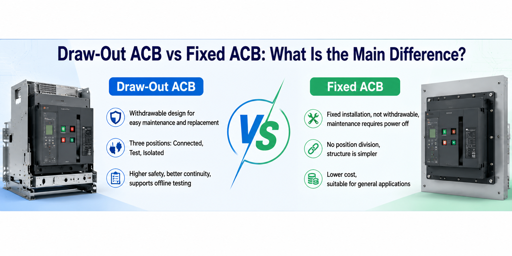
Draw-Out vs. Fixed ACB. Draw-out models feature a 3-position cradle for safe, offline maintenance, while fixed models offer a cost-effective alternative.
Quick Comparison Table
Comparison Item | Draw-Out ACB | Fixed ACB |
Installation Structure | Removable draw-out chassis, separate breaker body and base structure | Bolted fixed installation, integrated breaker body structure |
Standard Positions | Three positions: connected, test, and isolated | No position division |
Busbar Status During Maintenance | The busbar can remain energized; only the breaker body is disconnected | The busbar must be de-energized before maintenance |
Testing Method | Can be tested offline or without energizing the main circuit, safer and more reliable | Can only be tested online with power, higher risk |
Maintenance Difficulty | Easy to maintain, and the spare breaker body can be replaced quickly | More complicated to dismantle, requiring cable disconnection and re-tightening |
Power Supply Continuity | High, suitable for applications where power interruption is not allowed | Low, maintenance usually requires power shutdown |
What Is a Draw-Out ACB?
A draw-out ACB is an air circuit breaker installed inside a dedicated draw-out chassis. The breaker can be racked in or racked out from the switchboard without fully dismantling the main cabinet structure.
Both the main circuit and the secondary control circuit use separable plug-in connections, allowing the breaker body to be quickly connected to or disconnected from the busbar and control wiring. During maintenance, the switchboard busbar can remain energized, while the breaker is moved to a safe isolated position for inspection, commissioning, maintenance, or replacement.
A draw-out ACB also supports offline testing, so technicians do not need to perform load testing on the main circuit. This greatly reduces the risks of short circuits, electric shock, and incorrect operation.
Advantages: high safety, easy maintenance, quick replacement, and strong power supply continuity.
Disadvantages: more complex structure, higher cost, and larger overall size.
What Is a Fixed ACB?
A fixed ACB is an air circuit breaker that is directly installed and bolted inside the switchboard. Unlike a draw-out ACB, the breaker body cannot be racked in or racked out from a dedicated chassis.
The main circuit and secondary control circuit are usually connected by fixed terminals, busbars, or control wiring. During inspection, maintenance, or replacement, the main power supply usually needs to be shut down, and some wiring or busbar connections may need to be removed.
A fixed ACB has a simpler structure and lower cost, making it suitable for general low-voltage distribution systems where frequent maintenance, quick replacement, or high power continuity is not the main requirement.
Advantages: simpler structure, lower cost, smaller installation space, and easier cabinet design.
Disadvantages: less convenient maintenance, slower replacement, usually requires power shutdown, and lower flexibility compared with a draw-out ACB.
If you are still unsure about the difference between fixed ACBs and draw-out ACBs, you can visit our fixed ACB and draw-out ACB product pages to learn more about their differences in installation structure, maintenance convenience, and application scenarios.
Common Mistakes When Selecting an ACB
Many people select an ACB only based on rated current, while ignoring key factors such as breaking capacity, short-time withstand current, and protection coordination. As a result, the breaker may either fail to withstand real operating conditions or be unable to achieve selective protection, leaving potential safety risks in the power distribution system.
1. Only Checking Rated Current and Ignoring Breaking Capacity (Icu / Ics)
- Wrong practice: Believing that as long as the rated current is sufficient, the ACB can be used in all applications.
- Consequence: When the short-circuit current exceeds the ultimate breaking capacity of the ACB, the breaker may fail to extinguish the arc, which can burn the equipment or even cause an explosion.
- Correct practice: Select an ACB according to the prospective short-circuit current at the switchboard busbar, and choose an ACB with Icu ≥ prospective short-circuit current.For critical main distribution circuits, models with Ics close to or equal to Icu are generally preferred.
2. Ignoring Short-Time Withstand Current (Icw) and Only Checking Breaking Capacity
- Wrong practice: Only focusing on how much current the ACB can interrupt, without considering how long the breaker can withstand fault current.
- Consequence: Upstream and downstream breakers cannot achieve selective protection. Before the downstream breaker operates, the upstream ACB trips first, causing a large-area power outage.
- Correct practice: According to the protection delay requirements, select an ACB with Icw ≥ prospective short-circuit current, and make sure the withstand duration meets the system selectivity requirement, such as 1s / 3s.
3. Confusing the Application Scenarios of ACBs and MCCBs
- Wrong practice: Using a large-frame MCCB to replace an ACB, assuming that a high current rating is enough for a main incoming circuit.
- Consequence: The short-time withstand capability, selectivity, and maintainability of an MCCB may not meet the requirements of a main distribution system. During a fault, this can easily lead to protection miscoordination or failure to isolate the fault properly.
- Correct practice: For main incoming feeders, bus couplers, generator outgoing circuits, and other critical circuits, an ACB that complies with IEC 60947-2 should be used.
4. Protection Functions Do Not Match the Actual Requirements
- Wrong practice: Blindly choosing a fully functional trip unit, or selecting a basic model with insufficient functions.
- Consequence: Either the cost is wasted, or key protection functions, such as ground fault protection, are missing, causing the system to fail to meet safety requirements.
- Correct practice: According to the circuit type, such as incoming feeder / bus coupler / feeder, and the load characteristics, select the required protection stages L / S / I / G as needed, and make sure the parameters can be adjusted.
5. Ignoring the Installation Method and Maintenance Convenience
- Wrong practice: Choosing a fixed ACB for critical circuits just to save cost, or blindly selecting a draw-out ACB for ordinary non-critical circuits.
- Consequence: Critical circuits may require power shutdown during maintenance, affecting power supply continuity; for non-critical circuits, unnecessary cost may be added.
- Correct practice: Use draw-out ACBs for important circuits such as main incoming feeders, bus couplers, and generator circuits. Fixed ACBs can be used for ordinary feeder circuits to balance safety and cost.
6. Not Verifying Protection Coordination with Downstream Devices
- Wrong practice: Setting the protection parameters of upstream and downstream circuit breakers independently, without checking selectivity coordination.
- Consequence: During a fault, protection may trip at the wrong level, expanding the power outage range and affecting power supply reliability.
- Correct practice: match the upstream and downstream protection curves to ensure that the downstream breaker operates first while the upstream breaker remains closed.
FAQ Section
Q1: What is the main difference between an ACB (Air Circuit Breaker) and a VCB (Vacuum Circuit Breaker)?
A: The primary difference lies in the voltage application and the arc-extinguishing medium. ACBs are designed for low-voltage networks (typically under 1000V AC) and use ambient air and arc chutes to quench the arc. VCBs are used in medium-voltage networks (e.g., 11kV, 33kV) and extinguish the arc inside a highly sealed vacuum interrupter chamber. They serve entirely different sections of the power grid.
Q2: How often should an Air Circuit Breaker (ACB) be maintained?
A: In critical facilities like data centers or heavy manufacturing plants, a visual and mechanical inspection should be conducted annually. A comprehensive maintenance routine—including lubricating the draw-out cradle mechanism, cleaning the arc chutes, and performing secondary injection testing on the intelligent trip unit—should be executed every 3 to 5 years, depending on the operating environment (dust, humidity) and switching frequency.
Q3: Can two ACBs be used to build an Automatic Transfer Switch (ATS)?
A: Yes, absolutely. For extremely high-current applications (typically over 1600A) where standard ATS units reach their limits, two motorized ACBs are commonly used. By equipping them with motorized charging mechanisms, closing coils, and strict mechanical and electrical interlocks, they form a highly robust, heavy-duty transfer system perfectly suited for main generator synchronization.
Q4: Is the extra cost of a draw-out ACB really worth it over a fixed ACB?
A: If system downtime costs your facility money, the answer is a definitive yes. Replacing a damaged fixed ACB requires completely de-energizing the main busbar and spending hours unbolting heavy copper connections. A draw-out ACB can be cranked out to the "isolated" position and safely swapped with a spare unit in minutes, making the initial higher capital cost negligible compared to the savings in maintenance downtime.
Conclusion
Choosing the right ACB is not only about selecting a high current rating. A reliable ACB must match the actual short-circuit level, protection coordination requirements, installation method, and maintenance needs of the power distribution system.
For critical main distribution circuits, draw-out ACBs usually offer better safety and service continuity, while fixed ACBs are more suitable for general applications where cost and space are more important. In any project, correct selection and proper protection settings are essential to ensure safe, stable, and long-term operation of the low-voltage distribution system.
-
Air Circuit Breakers (ACB) Explained: Structure, Protection, and Main Distribution Applications
2026-05-24 22:21:27 -
AC-1 vs AC-3 Contactors: What Is the Difference and How to Choose?
2026-05-20 19:31:24 -
Surge Protector vs. Voltage Protector: What’s the Difference? (Complete Guide)
2026-05-18 17:50:53 -
Selection and Installation Guide for SPDs in Solar PV Systems
2026-05-16 12:54:43 -
Voltage Stabilizer vs. Over and Under Voltage Protector: What Is the Difference?
2026-05-14 14:37:10