


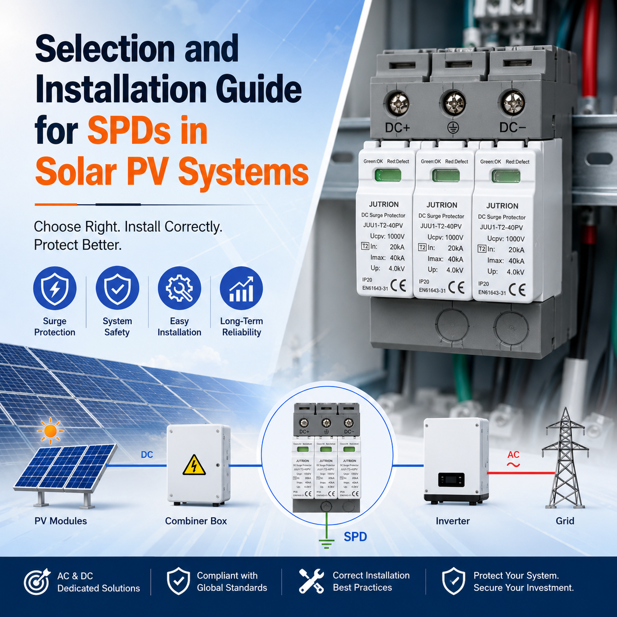
Selection and Installation Guide for SPDs in Solar PV Systems
In the operation of solar PV power plants, many failures are caused by invisible electrical surges. According to PV industry maintenance data, more than 30% of damaged PV inverters and combiner boxes are related to lightning induction and grid voltage fluctuations. However, the root cause of many small and medium-sized power plant failures is not the absence of SPDs, but incorrect parameter selection, improper installation location, and non-standard wiring.
Key Takeaways
Core Functions and Classification of PV SPDs
DC-Side SPD Selection
AC-Side SPD Selection
Complete Guidelines for Installation Location, Wiring, and Grounding
Common Misunderstandings in the PV SPD Industry
Routine Maintenance and Replacement Criteria for PV System SPDs
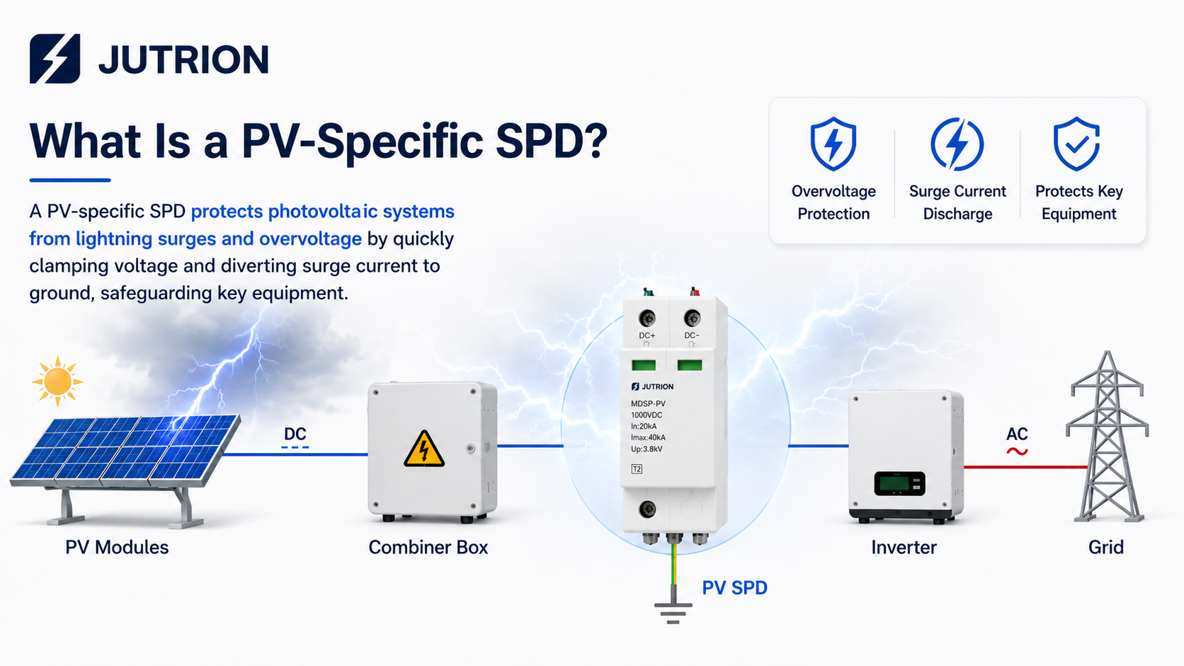
What Is a PV-Specific SPD?
An SPD, or surge protective device, is the “voltage safety valve” of a PV system. Its main function is to suppress transient overvoltage and discharge surge current. When lightning induction, grid switching, or sudden load changes cause abnormal high-voltage surges, the SPD can conduct within nanoseconds, discharge the surge current to the ground, and clamp the system voltage within a safe range. This helps protect PV modules, inverters, distribution cabinets, and other key equipment from breakdown damage.
Three Main Types of SPDs in PV Systems by Protection Level
PV power plants should configure SPDs in layers according to lightning risk and installation scenarios. The industry commonly uses three types of protection models to match different protection applications:
Type 1: First-level protection
Suitable for scenarios with high direct lightning risk, such as open ground-mounted PV power plants, mountain PV power plants, and power stations without building lightning protection shelters. It can discharge high direct lightning currents, with impulse current Iimp ≥ 12.5kA, 10/350μs. It is mainly installed at the main incoming line of the power station or the main combiner point of the PV array, serving as the first basic lightning protection barrier.
Type 2: Second-level protection
The most commonly used model in PV power plants, suitable for most residential, commercial, and industrial power stations. It is used to protect against induced lightning and switching overvoltage, with nominal discharge current In ≥ 20kA, 8/20μs. It is installed in combiner boxes and at the DC input side of inverters to provide refined protection for core equipment.
Type 1+2: Combined type
Integrates both first-level and second-level protection functions. It is suitable for high-lightning areas, renovation of old power stations, and distribution cabinets with limited space. It does not require layered installation and balances high-current discharge with precise voltage clamping, offering a good balance between cost performance and protection capability.
Different protection positions in a photovoltaic system require different types of surge protective devices, and special attention is needed during installation.
The table below summarizes common protection positions in PV systems, recommended SPD types, main protected objects, and installation suggestions. It can be used as a reference for procurement, engineering design, and on-site installation.
Protection Position | Recommended SPD Type | Main Protected Objects | Installation Suggestions |
PV combiner box / string side | Type 2 DC SPD or Type 1+2 DC SPDType 2 | PV strings, combiner busbars, DC input cables | For long-distance DC cables or areas with high lightning risk, protection at the source side is recommended. |
| Inverter DC input side | Type 2 DC SPDType 2 | Inverter MPPT, DC/DC modules, input terminal components | Install as close as possible to the inverter to provide terminal-side protection. |
Inverter AC output side | Type 2 AC SPDType 2 | Inverter AC output, AC grid connection circuit | Prevent surges from the grid side from entering the inverter in reverse. |
Building main distribution cabinet / grid-connected cabinet | Type 1 or Type 1+2 AC SPDType 1 | Main power system, energy meter, transformer low-voltage side | Should be prioritized when there is an external lightning protection system or overhead incoming line. |
Communication and monitoring lines | RS485 / Ethernet / PoE signal | Data collectors, switches, monitoring modules | Pay attention to interface type, transmission rate, and grounding method. |
Key Focus: Accurate Selection Guidelines for PV AC/DC Side SPDs
Many photovoltaic projects only focus on DC SPDs while ignoring the risks on the AC side. Grid switching transients, nearby lightning strikes, and building distribution faults may all affect the inverter through the AC side in reverse. Therefore, grid-connected PV systems should consider surge protection on both the DC side and AC side. AC SPDs should be properly installed at the inverter AC output side, AC combiner cabinet, and building main incoming line.
Key Selection Parameters for PV DC SPDs
The selection of photovoltaic DC SPDs should be based on the requirements of IEC 61643-31 for PV DC surge protective devices, combined with the system’s maximum open-circuit voltage, lightning risk level, installation environment, and the inverter’s withstand voltage level. During selection, users should not only consider the nominal voltage, but also pay close attention to Uc, In/Imax/Iimp, Up, and safety protection functions.
Uc is the most critical parameter in DC SPD selection.
Uc should not be lower than 1.2 times the maximum open-circuit voltage Voc-max of the PV string.
Common Engineering Selection Reference
PV System Voltage | Recommended DC SPD Voltage Rating |
600V DC system | Select 600V / 800V DC SPD |
1000V DC system | Select 1000V / 1200V DC SPD |
1500V DC system | Select 1500V DC or higher-grade dedicated |
Note
AC SPDs must not be used to replace DC SPDs, and lower-voltage SPDs must not be selected simply to reduce cost.
If you are not sure how to select a DC SPD for a 600V, 1000V, or 1500V photovoltaic system, you may refer to our detailed guide: 600V / 1000V / 1500V DC SPD Selection Guide.
Discharge Current Parameters: In / Imax / Iimp
In = Nominal Discharge Current
It is usually tested with an 8/20 μs waveform and is mainly used for Type 2 SPDs.
Imax = Maximum Discharge Current
It indicates the maximum surge current that the SPD can withstand under extreme conditions, and is commonly used to evaluate the product’s safety margin.
Iimp = Impulse Discharge Current
It is usually tested with a 10/350 μs waveform and is mainly used for Type 1 SPDs or Type 1+2 SPDs. It is suitable for scenarios with a high risk of direct lightning strikes.
Common Engineering Selection Recommendations
Application Environment | Recommended SPD Type | Suggested Parameters |
General areas with low annual lightning frequency | Type 2 DC SPDType 2 | In ≥ 20kA, 8/20 μsIn ≥ 20kA,8/20 μs |
Lightning-prone areas, open-ground power stations, long-distance DC cables | Type 2 DC SPDType 2 | In ≥ 40kA, 8/20 μsIn ≥ 40kA,8/20 μs |
High-risk ground power stations, overhead lines, buildings with external lightning protection systems | Type 1 or Type 1+2 DC SPD | Iimp ≥ 12.5kA, 10/350 μs |
Up = Voltage Protection Level
For PV DC-side SPDs, a lower voltage protection level should be selected. It is generally recommended that Up ≤ 2.5kV to reduce the risk of surge voltage damage to the inverter DC input side, MPPT module, and internal electronic components.
Under the condition that the system voltage rating and insulation coordination requirements are met, a DC SPD with a lower Up value should be prioritized.
Key Selection Points for AC Side SPDs
AC SPDs are usually installed at the inverter AC output side, AC combiner cabinet, grid-connected cabinet, or building main distribution cabinet. Their function is to prevent surge voltages from the grid side from entering the inverter in reverse, reducing the risk of damage to the AC output terminals, grid connection circuit, and internal electronic components.
Maximum Continuous Operating Voltage Uc
For a 380V three-phase grid-connected PV system, an AC SPD with Uc ≥ 420V is recommended. This allows the SPD to adapt to normal grid voltage fluctuations and helps prevent false operation under normal operating voltage.
Core Electrical Parameters
For general commercial and industrial PV systems or residential PV power stations, a Type 2 AC SPD is usually recommended, with In ≥ 20kA and Up ≤ 2.0kV.
Pole Configuration
For three-phase four-wire grid-connected PV systems, a 4P AC SPD must be selected to cover the three phase lines and the neutral line, providing complete AC-side surge protection. Missing phase or missing neutral configurations are strictly not allowed.
Common Engineering Selection Reference
Application Scenario | Recommended SPD Type | Suggested Parameters |
General commercial and industrial PV system | Type 2 AC SPD | Uc ≥ 420V, In ≥ 20kA, Up ≤ 2.0kV |
Lightning-prone areas or open outdoor PV stations | Type 2 AC SPD with higher discharge capacity | Uc ≥ 420V, In ≥ 40kA, Up ≤ 2.0kV |
Building with external lightning protection system or overhead incoming line | Type 1+2 AC SPD or Type 1 AC SPD | Iimp ≥ 12.5kA, 10/350μs waveform |
Three-phase four-wire grid-connected PV system | 4P AC SPD | Protect L1 / L2 / L3 / N lines |
Installation Note:
For three-phase four-wire grid-connected PV systems, a 4P AC SPD should be selected to protect all three phase lines and the neutral line. Do not use a three-pole SPD to replace a four-pole SPD, and do not omit the neutral line connection. Otherwise, the AC-side surge protection may be incomplete, especially when neutral-to-ground voltage rises or reverse surges occur from the grid side.
SPD Installation Points in PV Systems
DC Side Installation Points
When the PV string cable length is greater than 10 meters, or when the PV station is installed in an open and exposed outdoor environment, a DC SPD should be installed at the input side of the combiner box. This helps block induced surges from the PV string side.
A DC SPD should be installed at the inverter DC input terminal as the final stage of protection. This protects the inverter’s core components, such as the DC input circuit, MPPT module, and internal electronic components.
If the PV string cable length is less than 10 meters, a DC SPD may only be installed on the inverter DC side, provided that the protection requirements are met.
AC Side Installation Points
AC SPDs should be installed at the inverter AC output side, grid-connected distribution cabinet, or main distribution cabinet. The installation position should be close to the circuit breaker, grid connection switch, energy meter, or other key electrical equipment. This helps prevent grid-side surges from entering the PV system in reverse and damaging the inverter or downstream equipment.
SPD Wiring Rules: Keep Leads Short and Separate
To ensure reliable surge protection in PV systems, the following wiring rules should be followed:
Wiring Requirement | Recommended Practice | Purpose |
Shortest lead length | Keep the total SPD connecting cable length within 2.5 meters where possible. | Reduces inductive voltage drop and improves the clamping effect. |
V-shaped wiring preferred | Use “in-and-out” V-shaped wiring instead of long parallel leads. | Shortens the effective surge current path and improves protection performance. |
Separate DC and AC wiring | Route DC SPD cables and AC SPD cables separately. Do not share the same conduit or bundle them together. | Reduces electromagnetic coupling and avoids cross-interference between AC and DC surge paths. |
No series installation | SPDs must be installed in parallel with the protected circuit, not in series. | Prevents power interruption, overheating, or equipment failure caused by incorrect wiring. |
SPD Grounding and Installation Details
Proper grounding is essential for SPD performance. If the grounding path has high resistance, poor contact, or loose terminals, the surge current cannot be discharged quickly, and the SPD may fail to protect the inverter and other electrical equipment effectively.
Installation Item | Recommended Requirement | Explanation |
Grounding conductor | Use 16mm² multi-strand copper wire where possible. | Provides better current-carrying capacity for surge discharge. |
Grounding resistance | General requirement: ≤4Ω. In high lightning-risk areas, ≤1Ω is recommended. | Lower grounding resistance helps discharge surge current faster. |
Mechanical fixing | The SPD should be installed vertically and firmly, with enough heat dissipation space. | Prevents overheating and premature aging during long-term operation. |
Terminal connection | All terminals must be tightened securely. Avoid loose contact, false connection, or poor crimping. | Reduces the risk of heating, arcing, and protection failure. |
Outdoor installation | Outdoor SPDs should be installed in a waterproof enclosure with IP65 or higher protection level. | Suitable for rain, snow, dust, and long-term outdoor exposure. |
In PV systems, SPD installation should follow three basic rules: short wiring, reliable grounding, and correct installation position. Even if the SPD type and voltage rating are correct, poor wiring or grounding may still reduce its protection performance.
Common Mistakes in PV SPD Selection and Installation
Mixing AC and DC SPDs
Using ordinary AC SPDs to replace DC SPDs may show no abnormalities in the short term. However, after 3–6 months, continuous high-voltage aging may occur, and in thunderstorm weather, breakdown and short circuit may directly occur, burning the combiner box and inverter.
Installing Only AC SPDs and Not DC SPDs
80% of photovoltaic surges come from the DC array side. If only the AC side is protected, the core power generation equipment cannot be protected, which belongs to ineffective lightning protection.
Blindly Pursuing High Current Parameters
For ordinary residential power stations, blindly using SPDs above 40kA wastes cost and brings no actual benefit. Parameters only need to match the working conditions.
Treating Grounding Casually
The core of normal SPD operation is grounding. Excessive grounding resistance, false connection, or disconnection will prevent surge current from being discharged, making the SPD completely ineffective.
No Maintenance After Installation
SPD is a consumable protection device. Lightning strikes and long-term high-voltage operation will cause performance degradation. Once it fails, it has no protective effect and can easily cause equipment damage.
Routine Maintenance and Replacement Criteria for SPDs
An SPD is not a device that can be installed once and used permanently. Regular maintenance is the key to ensuring effective lightning and surge protection.
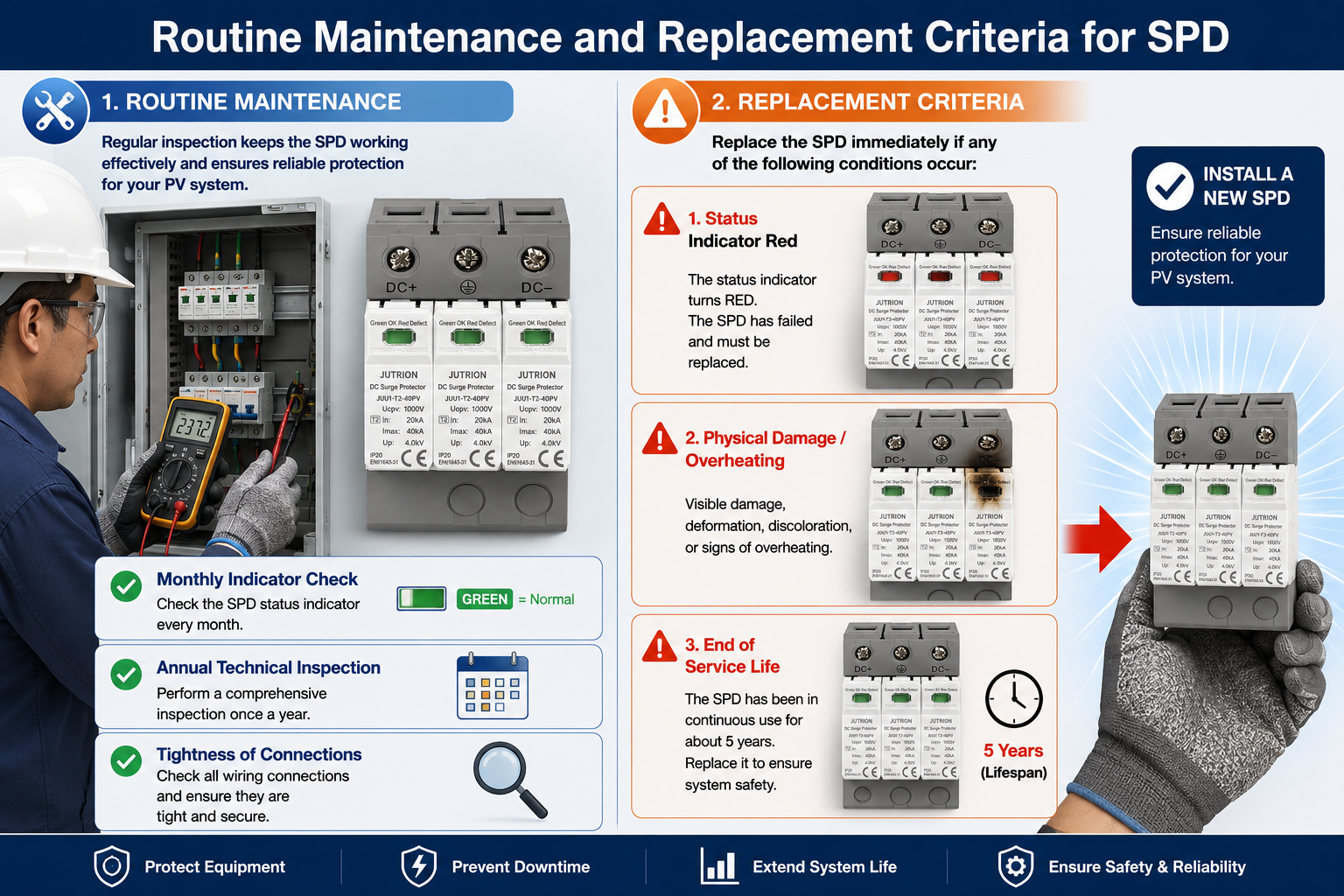
Infographic showing routine maintenance checks and replacement criteria for SPDs in solar PV systems.
Key Points for Routine Inspection
- Monthly visual inspection: Check the SPD status indicator. Green means normal; red or gray means failed and requires immediate replacement.
- Quarterly testing: Use a multimeter to check the voltage at both ends of the SPD and the grounding resistance, and inspect the wiring for looseness, aging, or damage.
- Special inspection after the thunderstorm season: After lightning strikes, focus on checking whether the SPD has been punctured or disconnected, and replace damaged devices in time.
Mandatory Replacement Criteria
- The status indicator turns red, the device is punctured, or the housing is deformed or overheated.
- After multiple lightning surge impacts, the performance parameters have declined beyond the standard limit.
- If the normal service life is less than 5 years, overall replacement is recommended to ensure protection performance.
- After power station expansion or voltage upgrade, replace the SPD with a model that matches the new system parameters.
FAQs:
Q: If my budget is limited, is it enough to install SPDs only on the AC side of the inverter?
A: No. Data shows that 80% of surge impacts in PV systems come from the DC array side. If protection is installed only on the AC side, it may result in ineffective lightning protection, because the most critical power generation equipment remains exposed to lightning risk. The proper approach is to install suitable SPDs on both the DC array side and the AC side.
Q: Is an SPD a one-time investment? When does it need to be replaced?
A: No. An SPD is a consumable safety device, not a permanently maintenance-free component. It should be inspected and replaced according to the following criteria:
Routine inspection: Check the SPD status indicator every month. Green means normal. If it turns red or gray, it means the internal components may have failed and the SPD must be replaced immediately.
After thunderstorm season: After strong lightning events, the SPD should be carefully inspected for damage or failure.
Mandatory replacement: If the housing is deformed, overheated, or the SPD has been in continuous use for around 5 years, replacement is recommended to ensure system safety.
Core Summary: The “Golden Rule” of Lightning Protection for PV Systems
The core logic of surge protection devices (SPDs) in PV systems can be summarized as: selection is the foundation, installation is the key, and maintenance is the guarantee.
To achieve the best protection effect, three key steps must be properly followed:
- Accurate Selection: AC and DC dedicated models must be strictly distinguished. During selection, the three core parameters — Uc (maximum continuous operating voltage), discharge capacity, and voltage protection level — should be carefully checked to ensure they match the specific voltage level of the power station and the on-site lightning risk.
- Proper Installation: During installation, the four basic principles of short lead wires, parallel installation, reliable grounding, and layered protection should be strictly followed. Safety risks caused by non-standard wiring must be avoided.
- Regular Maintenance: SPDs are not “once-and-for-all” devices. A regular inspection and timely replacement mechanism should be established. This is the only way to prevent failed SPDs from causing secondary safety accidents.
Whether for residential, commercial and industrial, or large ground-mounted PV power plants, installing a compliant SPD lightning and surge protection system at a relatively low cost can greatly reduce failure losses in inverters, PV modules, and distribution cabinets.
It not only effectively extends the service life of the entire power station, but also serves as the ultimate safeguard for ensuring the long-term stable, safe, and efficient operation of the PV system.
-
Selection and Installation Guide for SPDs in Solar PV Systems
2026-05-16 12:54:43 -
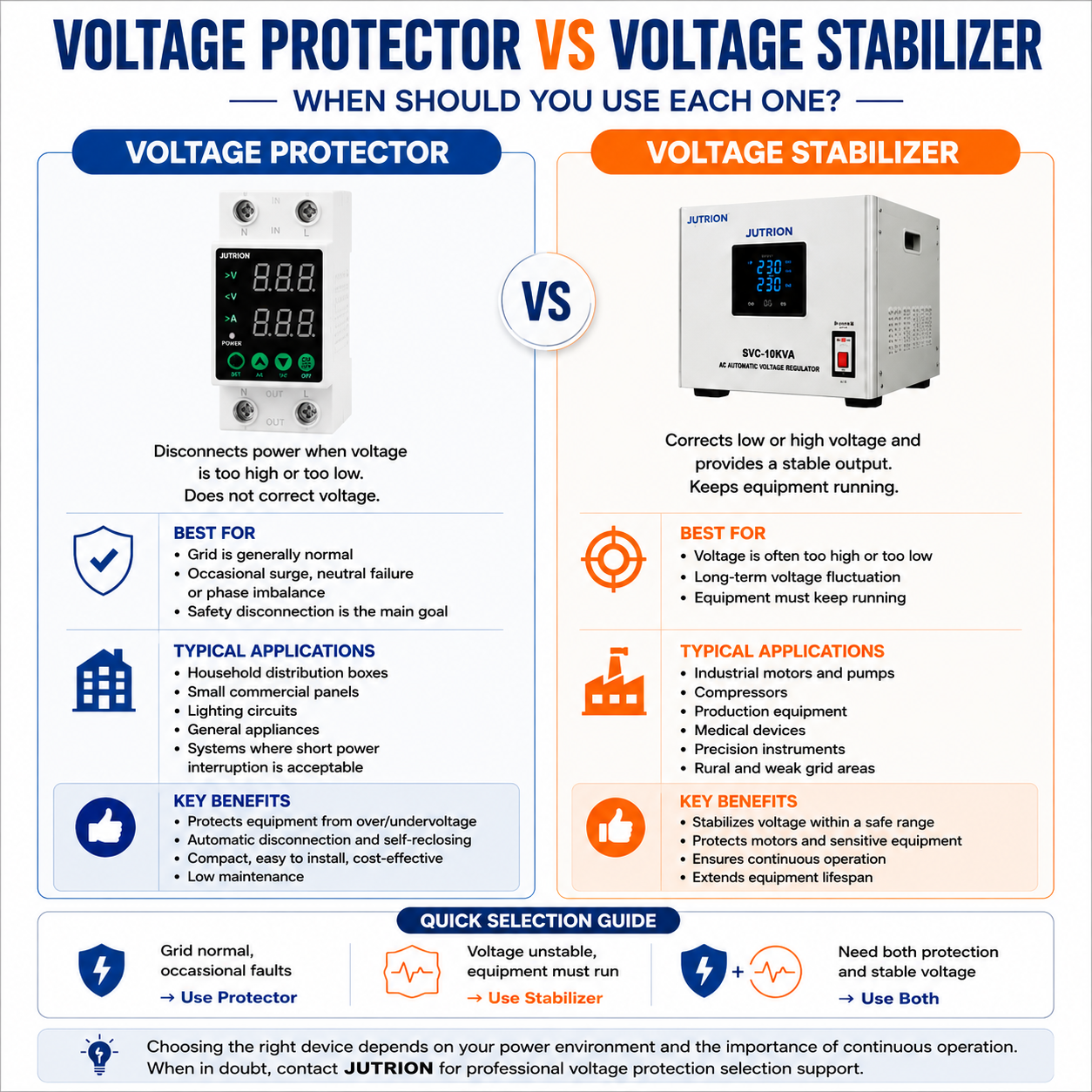
Voltage Stabilizer vs. Over and Under Voltage Protector: What Is the Difference?
2026-05-14 14:37:10 -
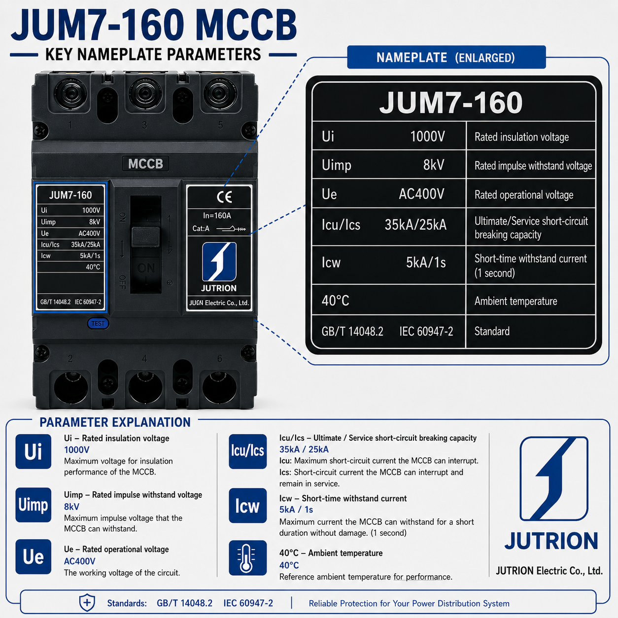
Confused by Icu, Ics and Icw? A Complete Guide to Understanding MCCB Nameplate Ratings
2026-05-12 17:31:01 -
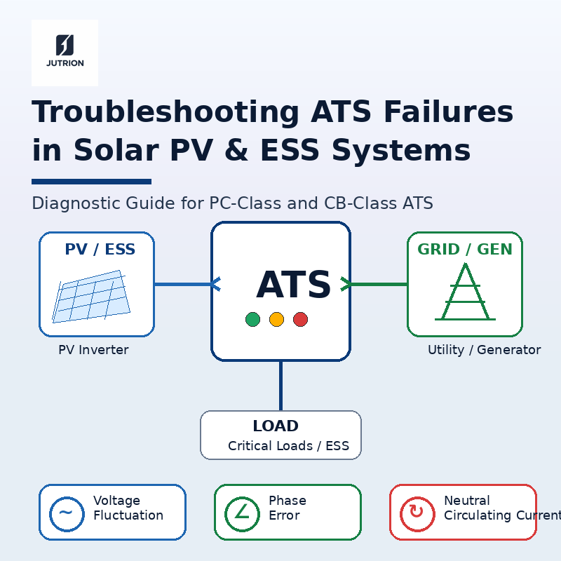
How to Troubleshoot PC-Class and CB-Class ATS Failures in Solar PV and Energy Storage Systems?
2026-05-10 17:04:51 -
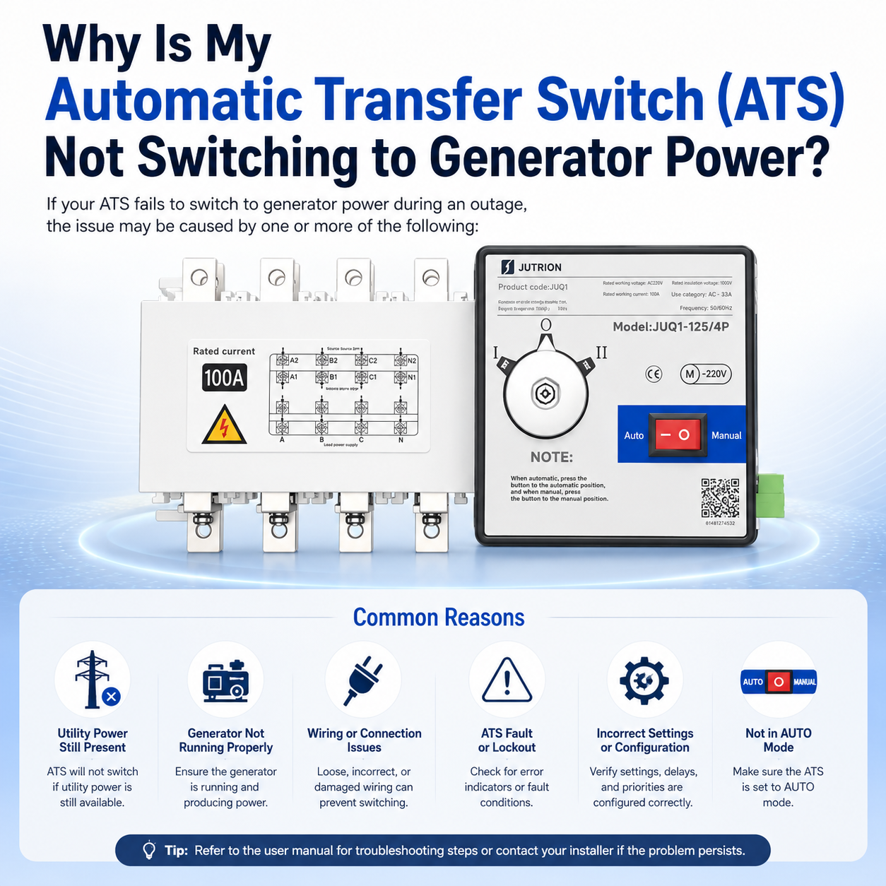
Why is My Automatic Transfer Switch (ATS) Not Switching to Generator Power?
2026-05-07 22:31:27