


How to Troubleshoot PC-Class and CB-Class ATS Failures in Solar PV and Energy Storage Systems?
We frequently receive inquiries regarding Automatic Transfer Switch (ATS) equipment, particularly in the context of Solar PV and Energy Storage Systems (ESS). Customers often report several recurring issues:
ATS failing to transfer during critical periods.
Frequent "chattering" (rapid back-and-forth switching) on cloudy days.
Nuisance tripping of breakers upon inverter startup.
Phase sequence faults and contact arcing/burning.
In reality, many of these problems are not caused by a damaged ATS itself. Instead, they stem from compatibility issues between traditional ATS logic and the unique electrical characteristics of modern inverters, energy storage systems, and power electronics.
In this article, we will combine real-world engineering scenarios to analyze the most common ATS failure causes in solar systems from the perspective of both CB-Class and PC-Class ATS structures, providing practical troubleshooting plans and solutions.
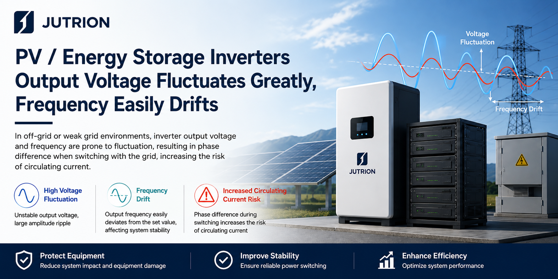
1. High Output Voltage Fluctuations from Solar/ESS Inverters
Imagine a cloudy afternoon; as clouds pass over the solar panels, the inverter's output power drops sharply. If your Automatic Transfer Switch (ATS) sensitivity is set too high, it will begin to "chatter" (rapidly switching back and forth). This behavior can lead to severe damage to the switch contacts and your connected electrical appliances.
Troubleshooting & Solutions Table:
| Type | Fault Phenomenon | Key Diagnostic Points | Corrective Actions |
| CB Class | Prone to undervoltage and overcurrent trip/lockout. | Measure voltage and frequency fluctuations; verify protection setpoints. | Widen undervoltage thresholds; reduce overcurrent sensitivity; enable Low Voltage Ride Through (LVRT) on the inverter. |
| PC Class | Failure to transfer or frequent back-and-forth switching (chattering). | Check controller sampling data; verify transfer delay settings. | Adjust voltage/frequency Tolerance; increase the transfer delay. |
2. Grid & Inverter Phase / Phase Sequence Asynchronization
When grid power returns, switching back while the inverter is "out of phase" is like two speeding trains colliding. This generates a massive Circulating Current that can weld contacts instantly or blow the inverter's power electronics.
Troubleshooting & Solutions Table:
| Type | Fault Phenomenon | Key Diagnostic Points | Corrective Actions |
| CB Class | Instantaneous magnetic trip and lockout during transfer due to surge. | Compare phase angle difference; check trip logs. | Enable grid-sync tracking; calibrate phase sequence; adjust overcurrent setpoints. |
| PC Class | Switch stuck in neutral; severe arcing and burnt contacts. | Verify phase sequence; inspect mechanical interlocks. | Enable Sync-check (In-phase Monitor); strictly prohibit manual forced paralleling. |
Understanding the Mechanism: How Phase Asynchronization Causes Damage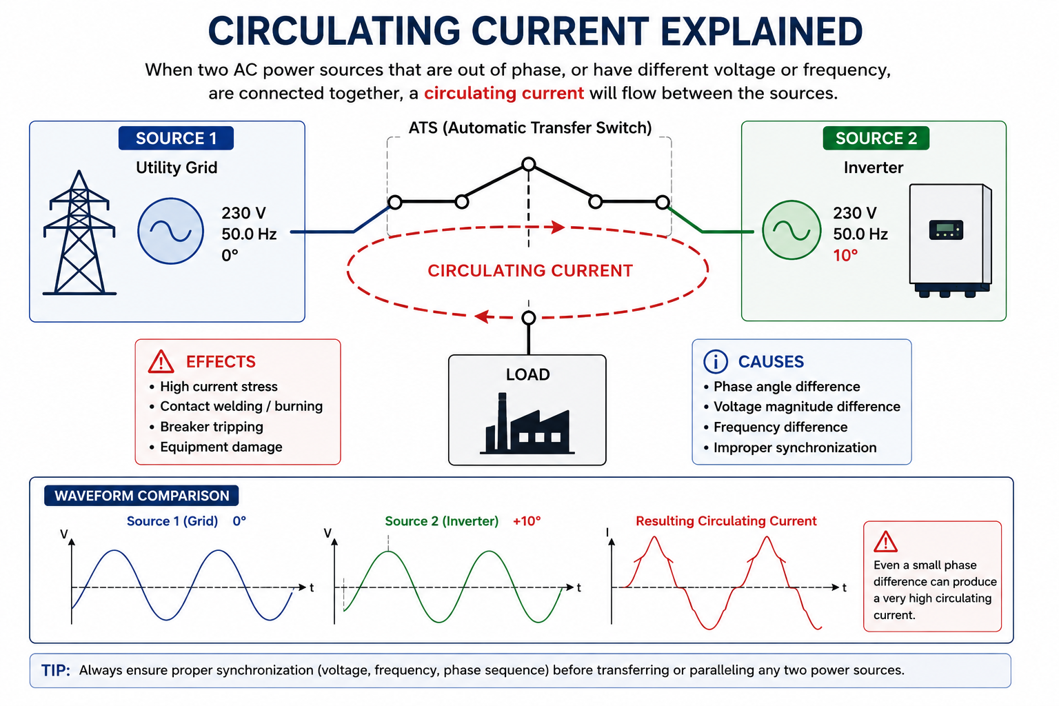
Figure: The relationship between out-of-phase AC sources and resulting circulating currents.
3. High Inverter Harmonics Interfering with Control Circuits
Some low-cost or aging inverters produce "dirty" power with high total harmonic distortion (THD). This electrical "noise" sneaks into the ATS controller's sensitive microcomputer, causing it to freeze, display garbled data, or trigger a switch at the wrong time.
For those unfamiliar with the definition of harmonics, please refer to the IEC 61000-3-2 and IEC 61000-3-12 standards for technical guidelines.
Troubleshooting & Solutions Table:
| Type | Fault Phenomenon | Key Diagnostic Points | Corrective Actions |
| CB Class | Nuisance tripping without any visible overload or short circuit. | Measure THD levels; check if control wiring is close to high-power cables. | Install AC filters; use shielded cables for control circuits. |
| PC Class | Chaotic sampling data on the screen; failure to execute transfer logic. | Inspect power supply interference; check if signal and power wires share the same conduit. | Install EMI filters; separate signal and power wiring into different conduits. |
4. Instantaneous Voltage Drop (Voltage Sag) in PV/ESS Systems
In an off-grid or hybrid solar setup, starting a high-power inductive load (e.g., an AC motor) can cause the inverter's output voltage to momentarily "dip" due to high inrush current. Without proper configuration, the ATS may misidentify this transient dip as a source failure, triggering an unnecessary and repetitive switching cycle.
Troubleshooting & Solutions Table:
| Type | Fault Phenomenon | Key Diagnostic Points | Corrective Actions |
| CB Class | Immediate undervoltage tripping when load is applied. | Use a waveform recorder to monitor the depth of voltage drop during load connection. | Use inverter soft-start; avoid switching ATS while high-power loads are active. |
| PC Class | ATS locks up and refuses to transfer due to detected voltage drop. | Check the undervoltage threshold parameters in the controller. | Increase undervoltage delay; implement staged load connection (step-loading). |
For technical definitions of voltage dips and their impact on switching equipment, refer to the IEC 61000-4-11 Standards.
Whether you should choose a PC or CB class switch depends heavily on your load profile. You can compare their performance features in our Detailed ATS Selection Table.
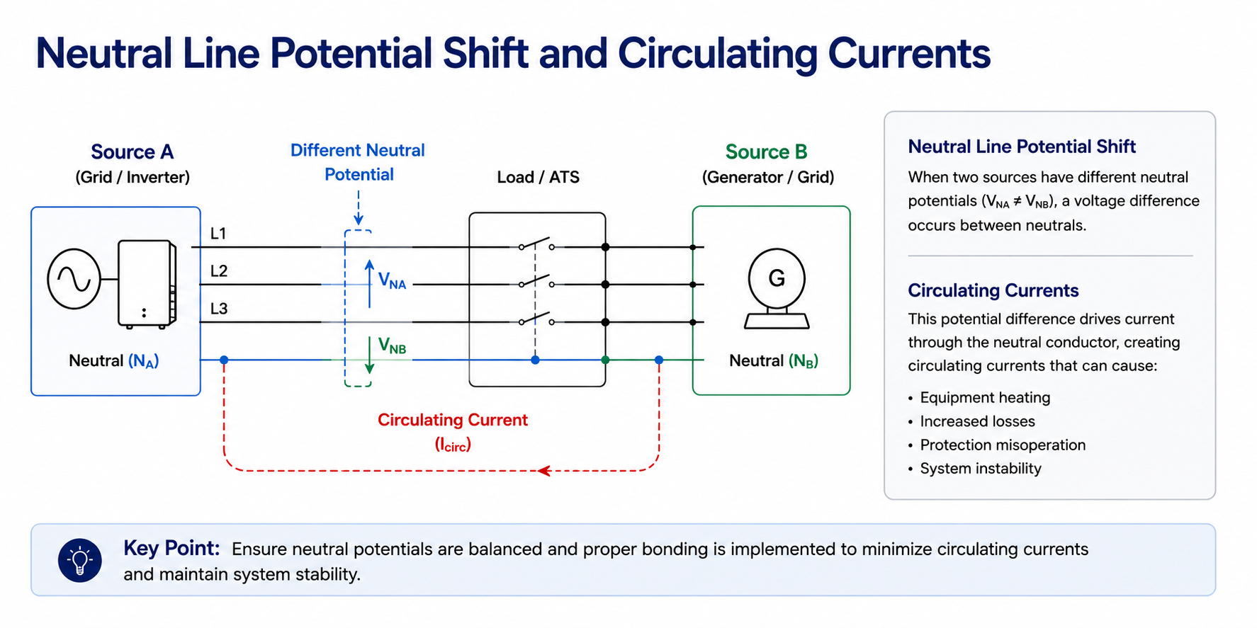
5.Neutral Line Potential Shift and Circulating Currents
In many solar hybrid systems, if the inverter's neutral is not properly referenced or if the ATS fails to isolate the neutral during a source switch, a "floating neutral" occurs. This can lead to a shift in neutral potential, causing connected 220V appliances to be exposed to high voltages, or creating a dangerous circulating current path that damages sensitive inverter electronics.
Diagnosing external control signal conflicts in intelligent solar power distribution.
Troubleshooting & Solutions Table:
| Type | Fault Phenomenon | Key Diagnostic Points | Corrective Actions |
| CB Class | Unexpected leakage protection trips; abnormal voltage on the neutral-to-earth line. | Check if the system requires a 4-Pole (4P) breaker; measure the voltage between Neutral and Ground. | Use a 4P ATS to ensure complete neutral isolation; verify the system grounding (TN-S or TT). |
| PC Class | Inverter reports "Ground Fault" or "Neutral Fault" during switching. | Inspect if the neutral lines from the grid and inverter are tied together (Neutral Overlapping). | Implement 4P switching; ensure the Neutral-to-Ground (N-G) bond is correctly managed during off-grid mode. |
6.Failure of Manual/Auto Mode and External Control Logic
In sophisticated PV systems, the ATS is often integrated with a Remote Monitoring System (RMS) or a fire alarm linkage. A common issue arises when the external controller sends a "forced neutral" signal during a routine system check or a software glitch. This prevents the ATS from switching automatically even when the power fails, leading to an unexpected blackout despite having full battery storage.
Troubleshooting & Solutions Table:
| Type | Fault Phenomenon | Key Diagnostic Points | Corrective Actions |
| CB Class | The external motor operator fails to reset; manual handle feels jammed. | Inspect the electrical interlocking circuit; check if the "Auto" mode switch is physically damaged. | Clear any physical obstructions; reset the control circuit power to clear the interlock state. |
| PC Class | The "Auto" light is on, but the switch refuses to transfer to the backup source. | Check the status of the "Remote Control" (RC) or "Fire Linkage" terminals; verify signal voltage. | Ensure no permanent "Force Neutral" signal is present; check the firmware settings of the ATS controller. |
Warning: Before inspecting control terminals or fire linkage signals, ensure all external control power is isolated. Incorrect wiring of forced-neutral signals can lead to permanent damage to the ATS control board.
Conclusion: Ensuring Maximum Uptime in Solar Applications
To build a truly resilient solar power system, selecting a high-quality ATS is only the first step. Success lies in the details of the configuration and an understanding of the inverter's electrical behavior.
The 6-Point Checklist for a Stable ATS Installation:
Widen Sensing Windows: Adjust voltage and frequency thresholds to accommodate common inverter fluctuations.
Prioritize Synchronization: Ensure phase-matching or use sufficient transition delays to eliminate circulating currents.
Filter the Noise: Deploy EMI filters and shielded control wiring to neutralize high-frequency harmonics.
Account for Inrush: Set a transfer delay (0.5s–2s) to bypass voltage sags during heavy motor startup.
Isolate the Neutral: Always use 4-pole switching to prevent potential shifts and leakage trips.
Verify External Logic: Regularly test remote control and fire linkage signals for logic conflicts.
Besides inverter-specific challenges, integrating a backup generator also requires careful logic configuration. If you are experiencing issues with power transfer in standby generator setups, see our specialized troubleshooting guide: Why is My Automatic Transfer Switch (ATS) Not Switching to Generator Power?
-
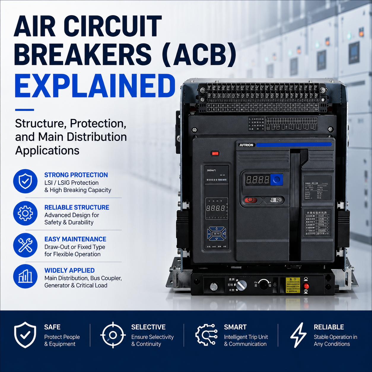
Air Circuit Breakers (ACB) Explained: Structure, Protection, and Main Distribution Applications
2026-05-24 22:21:27 -
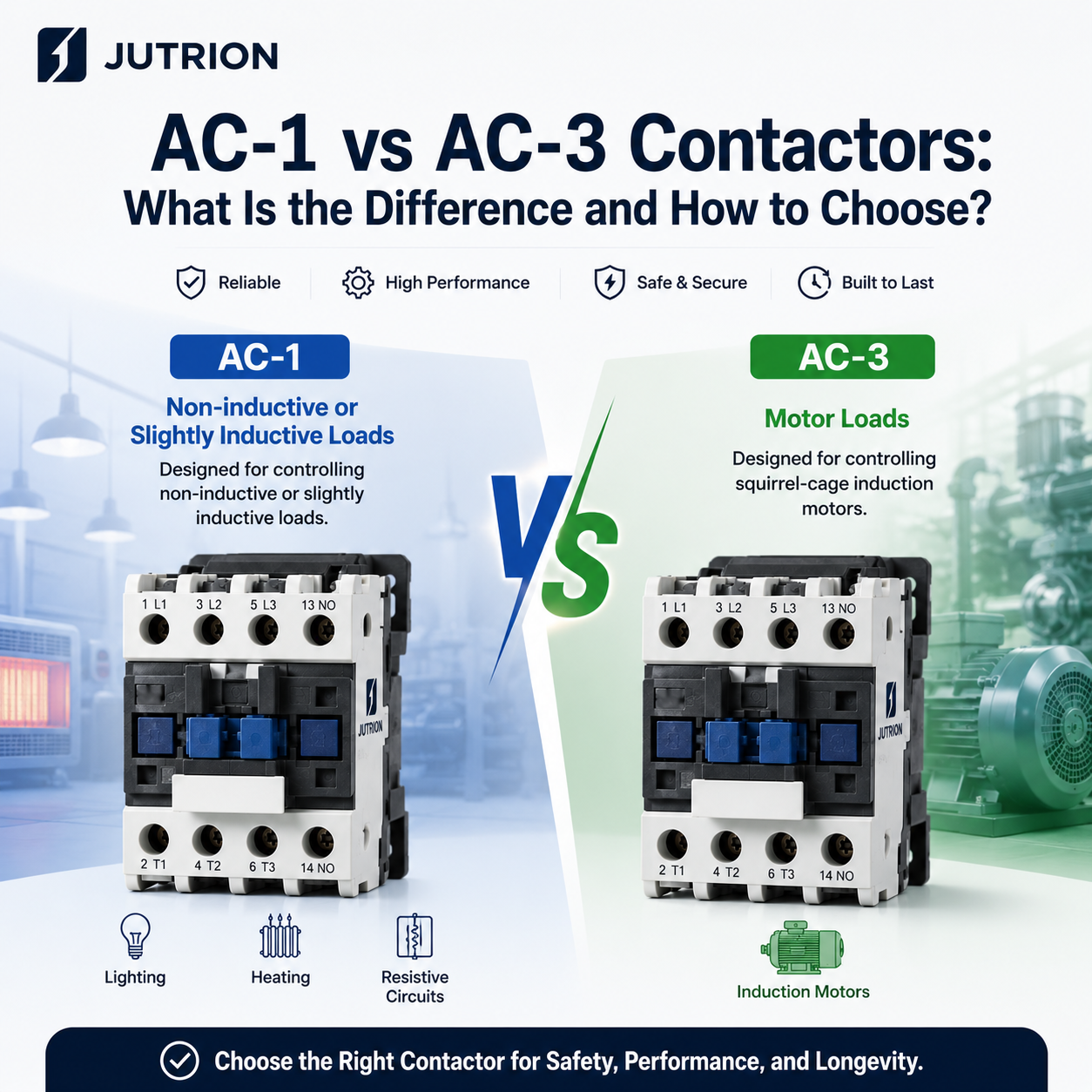
AC-1 vs AC-3 Contactors: What Is the Difference and How to Choose?
2026-05-20 19:31:24 -
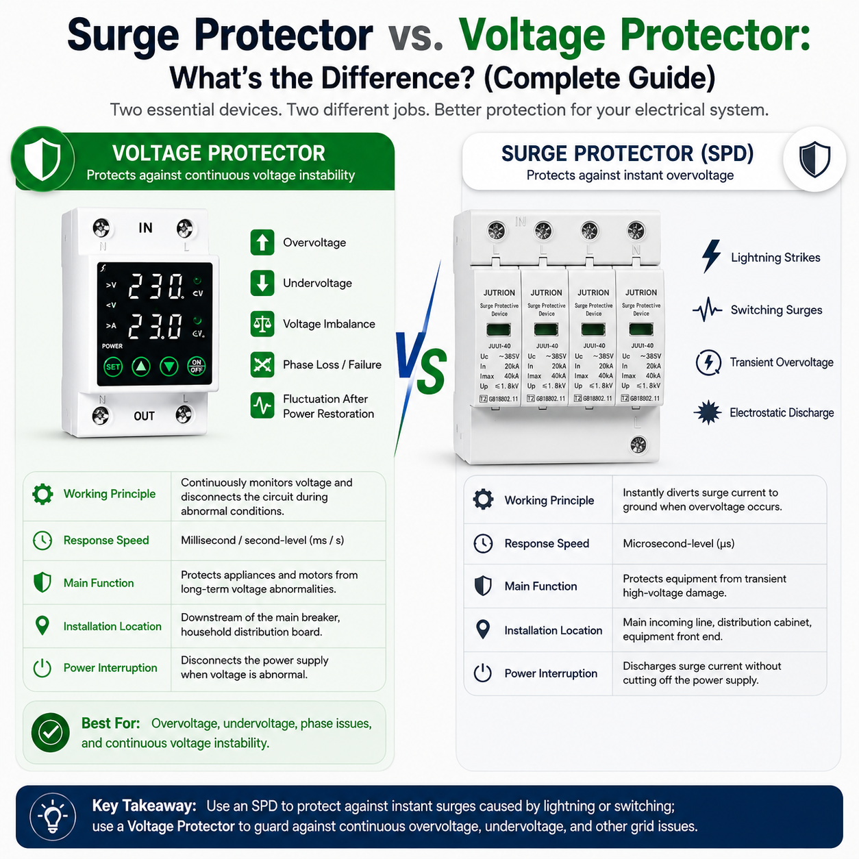
Surge Protector vs. Voltage Protector: What’s the Difference? (Complete Guide)
2026-05-18 17:50:53 -
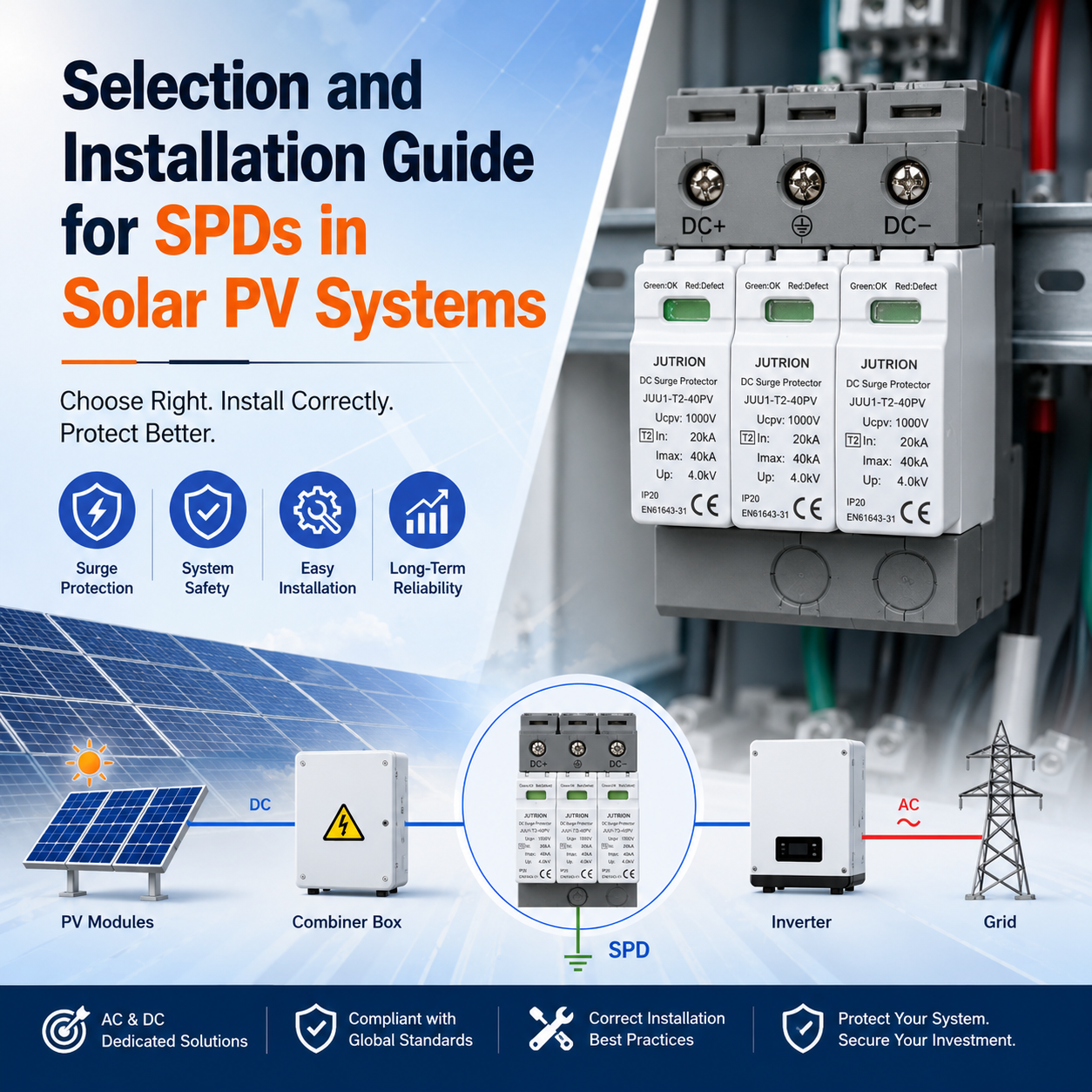
Selection and Installation Guide for SPDs in Solar PV Systems
2026-05-16 12:54:43 -
Voltage Stabilizer vs. Over and Under Voltage Protector: What Is the Difference?
2026-05-14 14:37:10