



How to Select the Right AC Contactor for Electrical Systems?
What Is an AC Contactor?
An AC contactor is one of the most common switching devices in electrical control systems. You can understand it as a power switch controlled by a weak-current control circuit. It is specially used in AC circuits to safely connect or disconnect high-power electrical equipment, such as motors, heaters, lighting systems, and other loads.
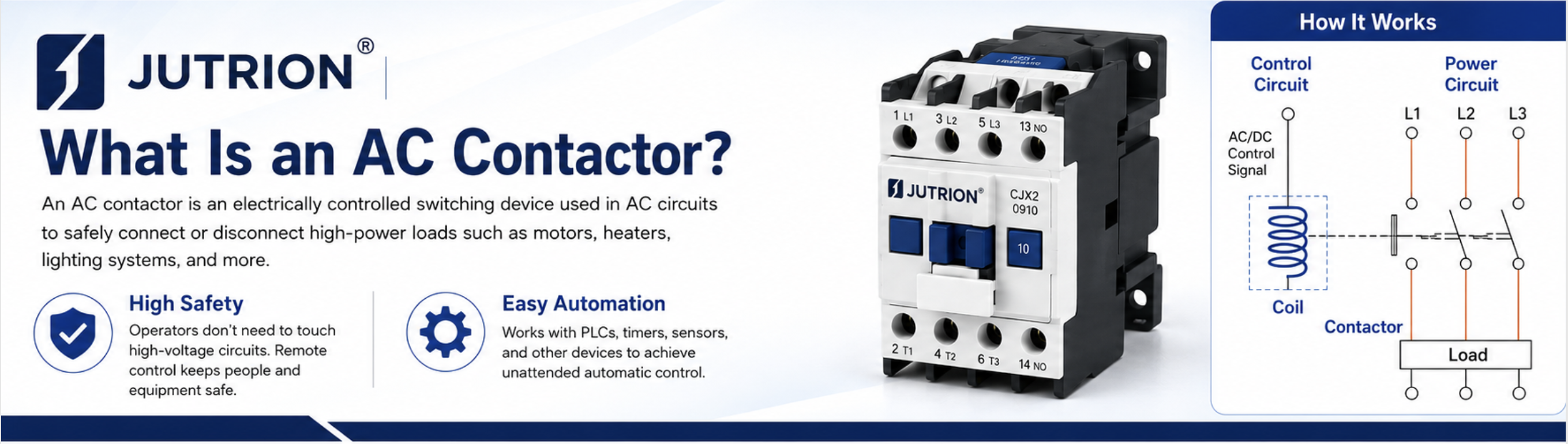
Its two most direct advantages are:
- High product safety: Operators do not need to directly touch high-voltage power circuits, and the equipment can be started or stopped remotely.
- Convenient automation: It can work together with PLCs, timers, sensors, and other devices to achieve unattended automatic control.
Simply put, a contactor is the “safe switch” used to connect and disconnect power circuits in industrial electrical control systems. It is also a basic component in automation and power distribution systems.
Main Components of an AC Contactor
Although different contactor models may vary in size, rated current, and installation method, most AC contactors are composed of several key components: main contacts, coil, auxiliary contacts, and arc chamber.
- Main contacts: They directly carry the high current of the main circuit and are responsible for connecting and disconnecting the load. They are the “power path” of the contactor.
- Coil: The coil is the driving core of the contactor. When energized, it generates a magnetic field that pulls the main contacts together, allowing switching control.
- Auxiliary contacts: These are low-current contacts used in control circuits. They can provide contactor status feedback or be used for interlocking and latching control.
- Arc chamber: The arc chamber is specially designed to extinguish the arc generated when the main contacts open. It helps prevent contact burning and ensures safe and reliable switching.
Why AC Contactor Selection Cannot Be Based Only on Current Rating
Selecting an AC contactor cannot be based only on rated current. The main reason is that current is only a basic parameter. The actual load condition, load type, and installation environment can greatly affect the real carrying capacity and service life of the contactor. If you select a contactor only by current rating, it is easy to make the wrong choice, causing contact burning, misoperation, or premature failure.
Below are the key reasons:
1. Different Load Types Have Very Different Working Currents
Even with the same rated current, different loads have completely different inrush currents and operating characteristics:
- Resistive loads such as heaters and incandescent lamps: the starting current is close to the operating current, so contactor selection is usually relatively simple.
- Inductive loads such as motors, pumps, and fans: the starting current can reach 5–7 times the rated current. The contacts must withstand short-time high-current impact. If you only look at the rated running current, the contacts may burn quickly.
- Capacitive loads, transformers, and capacitor banks: the closing inrush current can be very high, so the arc-extinguishing ability and contact performance requirements are higher.
2. Duty Cycle and Operating Frequency Affect Service Life
- Long-term continuous operation, short-time frequent starting and stopping, and jogging operation all have different requirements for contactors.
- Frequent switching, such as hundreds or thousands of operations per day, will cause arc accumulation and serious contact wear. Even if the static current matches, the contactor may still wear out quickly or the contacts may weld together. In this case, a contactor designed for high operating frequency should be selected.
3. Voltage Rating Determines Arc Extinguishing and Insulation Capability
- The rated operational voltage of a contactor is a key parameter. The higher the voltage, the longer the arc during breaking, and the more difficult it is to extinguish.
- For the same current rating, AC220V and AC380V cannot be used interchangeably. In high-voltage applications, phase-to-phase and phase-to-ground insulation must also be considered. Looking only at current may lead to arcing or short circuits.
4. The Installation Environment May Cause Derating
In high-temperature environments, sealed cabinets, dusty locations, humid conditions, or high-altitude areas, the heat dissipation performance of the contactor becomes worse. As a result, the actual allowable load current will automatically decrease, which means the contactor must be used with derating.
If you select a contactor only according to its nameplate current, it may cause overheating, tripping, and accelerated aging.
5. Control Circuit and Auxiliary Contact Requirements
- If the coil voltage is selected incorrectly, such as AC220V, AC380V, or DC24V not matching the control circuit, the contactor will not be able to pull in properly.
- The number and configuration of auxiliary contacts, such as normally open and normally closed contacts, determine whether the system can achieve latching, interlocking, signal feedback, and other control logic. Even if the current rating matches, the contactor may still fail to meet the control requirements.
6. Breaking Capacity and Short-Circuit Withstand Capability
When a short circuit occurs in the circuit, the contactor must work together with protective devices to withstand short-time short-circuit current.
- If you only consider the operating current and ignore the maximum breaking capacity, the contacts may weld together or burn out instantly during a short-circuit fault.
Simple Summary
Rated current is only a reference under steady operating conditions. Proper contactor selection must consider the following factors together:
Load type → Utilization category → Operating voltage → Operating frequency → Environmental conditions → Coil / auxiliary contacts → Breaking capacity
If any one of these factors is ignored, it may leave hidden safety risks.
Identify the Load Type and Utilization Category
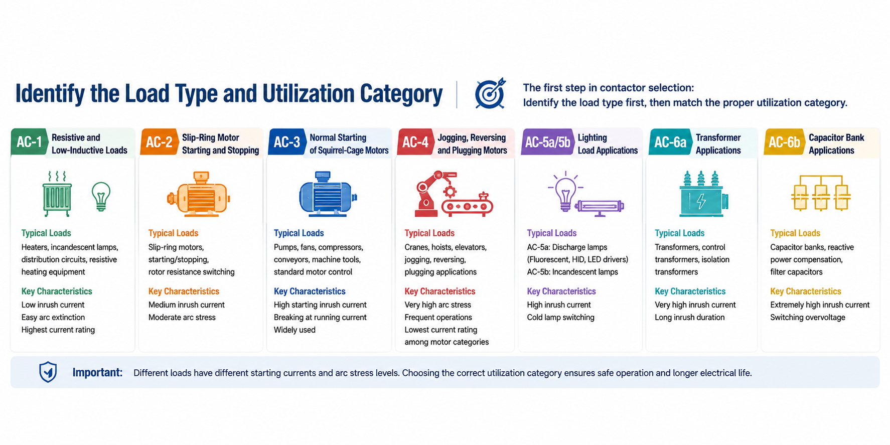
When selecting an AC contactor, the first priority is not to look at the current rating, but to identify the load type first and then match it with the corresponding utilization category. The utilization category is defined by the IEC 60947-4-1 standard. It directly determines the current impact, arc stress, and electrical life requirements that the contactor must withstand during making and breaking operations.
Different loads have very different starting characteristics. Even if the rated current is the same, the actual performance of the contactor may vary greatly.
Comprehensive Summary and General Selection Principles
✅ Define the Load First, Then Select the Category
The first step in selection is to identify the load type: use AC-1 for resistive loads, AC-3 for standard squirrel-cage motors, AC-4 for motors with frequent operation, AC-5 for lighting loads, AC-6 for transformers or capacitor banks, and AC-2 for slip-ring motors.
✅ Use the Parameters of the Corresponding Category
For the same contactor, the rated current is different under different utilization categories. Always check the rated operational current under the target category, and do not mix parameters from other categories.
✅ Apply Derating Based on Operating Conditions and Environment
For high-frequency switching, high-temperature environments, sealed cabinets, high-altitude areas, or dense installation of multiple devices, the current-carrying capacity should be reduced, and a larger contactor size should be selected.
✅ Do Not Mix Utilization Categories
Impact loads such as motors, lighting circuits, capacitors, and transformers must not be selected according to AC-1 resistive load parameters. This is one of the main causes of contactor failure.
✅ Match the Complete Protection System
A contactor is only responsible for normal making and breaking operations. It should be used together with circuit breakers, thermal overload relays, surge protective devices, and other components to build a complete control and protection system.
AC-1: Resistive and Low-Inductive Loads
This category applies to resistive loads and low-inductive load circuits. The circuit current waveform is stable, and there is no obvious inrush current during making and breaking. The arc energy during breaking is small, so the requirements for the contactor contacts and arc-extinguishing system are the lowest.
1. Electrical Characteristics of the Load
The load is mainly resistive, with a very low proportion of inductance. The current at the moment of equipment start-up is basically the same as the normal operating current. The making inrush current is usually ≤ 1.5 times the rated current. During the breaking process, the circuit voltage and current decrease synchronously, producing a short arc that is easy to extinguish.
2. Typical Application Scenarios
- Electric heating equipment: industrial electric heaters, resistance furnaces, constant-temperature drying ovens, heaters, and heating tube circuits.
- General distribution circuits: ordinary power distribution cabinets, lighting main circuits, and purely resistive power supply branches.
- Other low-inductive loads: small dry-type temperature control equipment and non-motor pure resistive electrical equipment.
3. Operating Conditions and Performance Requirements
- Switching frequency: It supports long-term continuous operation and can also be switched at normal operating frequency, with no strict frequency limitation.
- Contact requirements: The contacts do not need to withstand large current impact. Contact wear is slow, and the electrical life is long.
- Arc-extinguishing requirements: A standard arc-extinguishing structure can meet the application requirements, with no special arc-extinguishing configuration required.
4. Selection Key Points and Precautions
- AC-1 has the highest current-carrying capacity among all utilization categories. For the same contactor, the rated current under AC-1 is usually higher than that under motor categories such as AC-3 and AC-4.
- During selection, it is only necessary to ensure that the AC-1 rated current of the contactor is higher than the maximum operating current of the load, with a normal safety margin reserved.
- It is strictly forbidden to apply the AC-1 selection standard to impact loads such as motors, capacitors, and high-power lighting.
- If your project mainly involves standard motor control and you are unsure about the selection difference between AC-1 and AC-3, you can refer to our dedicated document: AC-1 vs AC-3 Contactor Selection Guide. This guide explains in detail the difference between resistive loads and motor loads, as well as why the same contactor may have different rated current values under different utilization categories.
Common Failure Risks Caused by Incorrect Selection
If an AC-1 rated contactor is forcibly used to control impact loads, the contacts may fail to withstand the instantaneous high current. This can lead to a prolonged arc, contact burning, increased contact resistance, equipment overheating, tripping, and other failures.
AC-2: Slip-Ring Motor Starting and Stopping
This category is specially used for the making, operation breaking, and rotor circuit switching of slip-ring asynchronous motors, including normal operating conditions such as motor starting, normal stopping, and rotor resistance switching.
1. Electrical Characteristics of the Load
When a slip-ring motor starts, rotor current-limiting resistance is connected, so the starting inrush current is lower than that of a squirrel-cage motor, generally 2–3 times the rated current. During operation breaking, the current is close to the motor’s rated operational current, and the arc load is moderate.
2. Typical Application Scenarios
- Main circuit control of high-power slip-ring asynchronous motors.
- Traditional heavy-duty wound-rotor motor systems, such as lifting equipment, large winches, and mine hoists.
- Starting and stopping circuits for slip-ring motors in old industrial equipment and dedicated transmission equipment.
3. Operating Conditions and Performance Requirements
- Operating characteristics: Mostly used for heavy-load starting and smooth speed regulation applications, with a medium starting and stopping frequency.
- Contact requirements: The contacts must withstand the short-time inrush current during motor starting, and their arc resistance must be higher than that required for AC-1.
- Structural requirements: A conventional standard contactor is generally suitable, with no need for a reinforced contact structure.
4. Selection Key Points and Precautions
- At present, the application of slip-ring motors in the industrial field is gradually decreasing, so the actual field usage rate of this category is relatively low.
- AC-3 category parameters cannot be used to replace AC-2 selection, because the assessment standards for making and breaking are different.
- If the motor involves plugging, frequent jogging, or reversing operation, AC-2 should not be selected. The selection should be upgraded to AC-4.
Common Failure Risks
When the operating conditions exceed the AC-2 range, such as frequent reversing or jogging, the contacts may repeatedly withstand high-current breaking. This can accelerate aging and cause premature failure.
AC-3: Normal Starting and Stopping of Squirrel-Cage Motors
This is the most widely used utilization category in industrial applications. It is intended for the standard operating conditions of direct starting and breaking during normal operation of squirrel-cage asynchronous motors, and it is also the mainstream reference category marked on contactor manufacturers’ nameplates.
1. Electrical Characteristics of the Load
A squirrel-cage motor is a typical highly inductive load. The cold-start inrush current can reach 5–7 times the rated current. Under this operating condition, the contactor only makes the circuit when the motor is at standstill, which means it withstands the starting inrush current. During breaking, the motor is already running normally and the current has dropped back to the rated value, so the breaking current is small and the arc is relatively weak.
2. Typical Application Scenarios
- General fluid equipment: industrial water pumps, centrifugal fans, exhaust fans, and cooling tower fans.
- Compressed air and conveying equipment: air compressors, material conveyors, oil pumps, and pump sets.
- General electromechanical equipment: machine tool main motors, small processing equipment, and complete motor control cabinets.
- Civil and commercial power equipment: central air-conditioning main units and ventilation units.
3. Operating Conditions and Performance Requirements
- Switching frequency: Suitable for normal industrial starting and stopping frequency. It supports long-term continuous operation and multiple starts and stops per day.
- Contact requirements: The contacts must withstand the high current impact at the moment of motor starting. Their resistance to welding and burning is much higher than that required for AC-1.
- Arc-extinguishing requirements: Equipped with a dedicated arc chamber to meet the arc-extinguishing requirements during motor breaking.
4. Selection Key Points and Precautions
- For most AC contactors on the market, the rated current is marked by default according to AC-3 category parameters. Standard motor applications should be selected based on this category first.
- Selection basis: use the motor nameplate full-load current (FLA) as the reference. Do not estimate only by motor power in kW.
- Environmental derating: in high-temperature environments, sealed cabinets, or when multiple contactors are densely installed, the actual usable current should be reduced, and a larger contactor size should be selected.
- Safety margin: under normal operating conditions, it is recommended to reserve a 10%–20% current margin. For heavy-load continuous operation, it is recommended to reserve more than 25% margin.
Common Failure Risks
- Selecting according to AC-1 current for an AC-3 application: the starting inrush current may burn the contacts, causing contact welding and failure to open.
- Undersized current selection: long-term overload heating, insulation aging, leakage, and tripping may occur.
AC-4: Jogging, Reversing and Plugging of Squirrel-Cage Motors
This category is designed for severe making and breaking conditions of squirrel-cage asynchronous motors. It is suitable for applications such as frequent breaking while the motor is running, jogging, reversing, and plugging. It is the utilization category with the highest requirements in motor control.
1. Electrical Characteristics of the Load
This is the most severe operating condition. The contactor needs to directly break the circuit while the motor is running at high speed or while the rotor has not stopped. At this moment, the breaking current can reach 3–5 times the rated current, and reverse electromotive force is also involved. The arc energy is extremely strong, and the current impact and arc load are much higher than those in AC-3 applications.
2. Typical Application Scenarios
- Frequent jogging equipment: small punch presses, drilling machines, robotic arms, and process equipment with short repetitive movements.
- applications: travelling cranes, gantry cranes, winding equipment, bidirectional conveying mechanisms, and turning machines.
- Plugging applications: transmission equipment that requires quick stopping or emergency braking.
- High-frequency starting and stopping equipment: automated production lines and reciprocating processing equipment with extremely high switching frequency per hour.
3. Operating Conditions and Performance Requirements
- Switching frequency: Suitable for ultra-high-frequency switching applications, with strict requirements for electrical life and mechanical life.
- Contact requirements: Thickened silver alloy contacts and reinforced contact structures are used to improve resistance to current impact, welding, and arcing.
- Arc-extinguishing requirements: Equipped with a reinforced arc chamber and multiple arc splitter plates to quickly extinguish high-energy arcs.
- Overall structure: Some dedicated AC-4 contactors optimize contact pressure and operating speed to reduce arc residence time.
4. Selection Key Points and Precautions
- For the same contactor, the rated current under the AC-4 category is much lower than that under AC-3, so AC-3 parameters cannot be directly applied.
- Standard AC-3 contactors are not recommended for long-term AC-4 operating conditions. Priority should be given to dedicated models with AC-4 parameters marked by the manufacturer.
- The higher the starting and stopping frequency, and the more frequent the reversing operation, the larger the selection margin should be.
- For supporting components, it is recommended to use surge suppression devices to suppress the high reverse electromotive force generated during breaking.
Common Failure Risks
If a standard AC-3 contactor is used instead of an AC-4 contactor, severe contact burning, contact welding, mechanical jamming, or even phase-to-phase short circuits may occur within a short time.
AC-5a / AC-5b: Lighting Load Applications
This category is specially designed for different types of lighting loads. According to the lamp type, it is divided into two subcategories, mainly used to handle the inrush current generated when lamps are switched on.
1.Electrical Characteristics of the Load
Lighting loads commonly have cold-state closing inrush current. When the lamp is not yet lit, its resistance is very low, so the instant of energization may generate an inrush current several times higher than the normal operating current. Different lamps may have significant differences in inrush current magnitude and duration.
Subcategories and Corresponding Applications
AC-5a: Gas-Discharge Lamp Circuits
- Applicable loads: fluorescent lamps, high-pressure sodium lamps, metal halide lamps, LED drivers, neon lamps, and other gas-discharge lamps with ballasts or drivers.
- Load characteristics: high closing inrush current. Since the ballast is an inductive component, the load has both inrush current and inductive characteristics.
- Application scenarios: factory lighting, road lighting, public lighting in shopping malls, and main lighting circuits in industrial areas.
AC-5b: Incandescent Lamp Circuits
- Applicable loads: traditional incandescent lamps, tungsten-halogen lamps, and other purely resistive light-emitting lamps.
- Load characteristics: the cold filament resistance is very low. The closing inrush current can reach 8–12 times the normal current, with a high peak value and short duration.
- Application scenarios: lighting in old buildings, local high-intensity lighting, and temporary lighting circuits.
4. Operating Conditions and Performance Requirements
- Key evaluation point: The contactor must withstand high-frequency closing inrush current and instantaneous high-current impact on the contacts.
- Switching frequency: Suitable for regular daily switching in lighting systems, with a medium operating frequency.
5. Selection Key Points and Precautions
- In lighting circuits, AC-1 resistive load parameters must not be directly applied. Selection must be based on AC-5a / AC-5b.
- When multiple lamps are controlled together, the total closing inrush current will increase. Therefore, the contactor size should be further enlarged.
- LED lamps with driver power supplies are capacitive loads with stronger inrush current characteristics, so an appropriate safety margin is recommended.
Common Failure Risks
If a standard AC-1 contactor is used to control a lighting circuit, it may be exposed to repeated closing inrush current over a long period. This can cause contact pitting, oxidation, poor contact, lamp flickering, or circuit disconnection.
AC-6a / AC-6b: Transformer and Capacitor Bank Applications
This category is designed for two typical types of capacitive / high-inrush loads: transformers and power capacitor banks. These loads can generate extremely high magnetizing inrush current or capacitive inrush current at the moment of closing, so they are considered high-risk operating conditions.
1. Electrical Characteristics of the Load
The two types of loads have one common feature: the equivalent impedance at the moment of closing is close to zero. The inrush current peak can reach 10–20 times the rated current, which is the highest among common load types. During breaking, switching overvoltage may also occur, placing very high requirements on the contactor coil, arc-extinguishing capability, and insulation performance.
2. Subcategories and Corresponding Applications
AC-6a: Transformer Circuits
- Applicable loads: dry-type transformers, oil-immersed transformers, control transformers, and primary circuits of isolation transformers.
- Load characteristics: transformer core magnetization produces magnetizing inrush current. The inrush current decays relatively slowly and lasts for a longer time.
- Application scenarios: dedicated workshop distribution transformers, built-in equipment transformers, and building distribution transformer circuits.
AC-6b: Capacitor Bank Switching Circuits
- Applicable loads: low-voltage reactive power compensation capacitor banks, filter capacitor banks, and energy storage capacitor circuits.
- Load characteristics: the capacitor charging inrush current peak is extremely high, and the residual capacitor voltage may superimpose and generate overvoltage.
- Application scenarios: factory reactive power compensation cabinets, distribution room capacitor compensation systems, and harmonic mitigation equipment.
3. Operating Conditions and Performance Requirements
- Contact requirements: High welding-resistant contact materials should be used to withstand extremely high instantaneous inrush current.
- Insulation requirements: Reinforced phase-to-phase and phase-to-ground insulation structures are required to withstand switching overvoltage during breaking operations.
- Arc-extinguishing requirements: A high-performance arc-extinguishing system is required to handle high-current breaking arcs.
4. Selection Key Points and Precautions
- Transformer and capacitor circuits are special high-risk loads. Dedicated AC-6a / AC-6b categories must be strictly used, and AC-1 or AC-3 contactors must not be used as substitutes.
- For capacitor switching applications, it is recommended to use dedicated capacitor switching contactors with current-limiting resistor structures to suppress closing inrush current.
- When multiple transformers or multiple capacitor banks are switched in parallel, the inrush current will be superimposed, so the contactor size must be significantly enlarged.
- For supporting protection, circuit breakers, surge protective devices, and other protective components must be installed to suppress overvoltage and short-circuit faults.
Common Failure Risks
If the wrong utilization category is selected, the huge inrush current at the moment of closing may directly cause contact welding, contactor rupture, phase-to-phase short circuits, large-area power outages, and equipment damage.
Selection of Rated Operating Current and Voltage
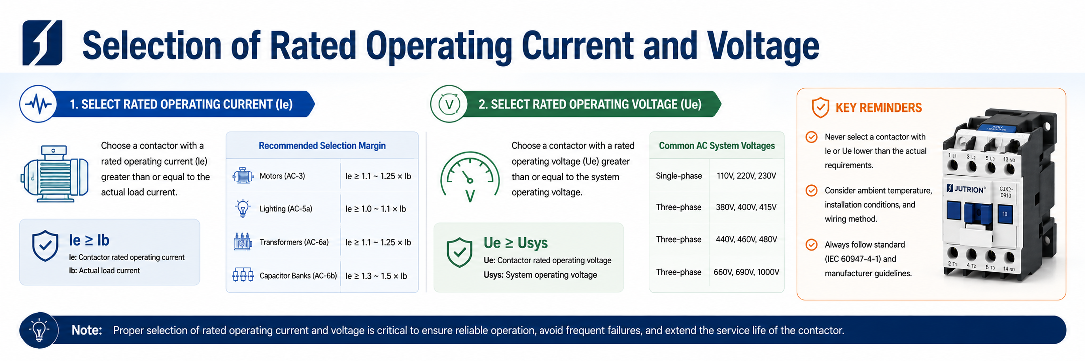
After the contactor utilization category is confirmed, the rated operational current and rated operational voltage must be accurately matched. These are two core parameters. At the same time, the actual power supply specification and load conditions on site should also be considered. This is the key to ensuring safe, stable, and long-term operation of the contactor.
1. Rated Operational Current Matching
Rated operational current refers to the current value that the contactor can carry for a long time under the corresponding utilization category and standard operating conditions, while keeping the temperature rise within the specified limits.
For the same contactor, the rated current may vary greatly under different utilization categories. Current parameters from different categories must not be mixed. The selection must be based on the utilization category corresponding to the actual load.
- General resistive loads and distribution circuits (AC-1):
The contactor has the highest allowable current-carrying capacity. It is usually enough to ensure that the rated current is higher than the normal operating current of the load, with a regular safety margin of 10%–20% reserved. - Standard motor loads (AC-3):
The full-load current marked on the motor nameplate should be used as the only selection reference. The current must not be estimated only by motor power in kW. For long-term full-load operation, outdoor high-temperature environments, poor heat dissipation in sealed cabinets, or dense installation of multiple devices, the current margin is recommended to be increased to more than 25%. - Severe motor applications with frequent jogging, reversing, or plugging (AC-4):
Under this category, the rated current of the contactor is greatly reduced. The corresponding product specification must be selected, and the selection margin should be further increased to avoid rapid contact burning caused by frequent high-current impact. - Lighting, transformer, and capacitor loads (AC-5 / AC-6):
These loads have extremely high closing inrush current. In addition to checking the rated current, dedicated contactor categories must be selected. For multiple circuits switched in parallel, the contactor size should be further enlarged.
2. Rated Operational Voltage Matching
The rated operational voltage determines the contactor’s insulation performance, voltage withstand level, and arc-extinguishing capability. The rated operational voltage of the contactor must be equal to or higher than the actual operating voltage of the circuit. Low-voltage products must never be connected to high-voltage circuits. Based on the common voltage levels used in industrial control sites, they can be classified as follows:
DC 24V (24VDC)
This is commonly used in automation control cabinets, PLC control systems, and small industrial control equipment. It is the most common voltage for low-voltage control circuits. When selecting a 24VDC contactor, it should be matched with a DC power supply circuit, and the insulation and arc-extinguishing structure must be suitable for DC arc characteristics.- AC 110V (110VAC)
This is widely used in imported equipment, complete machinery, and machine tool control circuits. It is an internationally common control voltage. During selection, AC specifications must be clearly distinguished to ensure that the coil voltage is consistent with the main circuit voltage. - AC 220V (220VAC)This is the mainstream voltage for domestic civil, commercial equipment, and single-phase power circuits. It is commonly used in lighting circuits, single-phase motors, and small heating equipment, and has the widest range of applications.
- AC 380V (380VAC)This is the standard voltage for industrial three-phase power systems. It is mainly used for high-power loads such as three-phase asynchronous motors, large compressors, pumps, and fans. It is also the core voltage level of industrial main circuits.
The higher the circuit voltage, the longer and stronger the arc generated during switching. If the voltage selection does not match, faults such as incomplete arc extinguishing, flashover, leakage, and phase-to-phase short circuits may occur. In serious cases, it may cause equipment burnout or cable fire.
3. Comprehensive Selection Precautions
- Current and voltage parameters complement each other and must be matched at the same time. Neither can be ignored. If only the current meets the requirement but the voltage does not, or if the voltage matches but the current is too small, the contactor may become overloaded, fail, or be damaged prematurely.
- Distinguish between the main circuit voltage and the coil control voltage. The main circuit voltage should be selected according to the load power supply specification, while the contactor coil voltage should be determined according to the control circuit power supply on site. Common specifications include 24VDC, 110VAC, 220VAC, and 380VAC. These two voltages can be configured independently and must not be confused.
- For applications with voltage fluctuation or short-time overvoltage, priority should be given to models with better voltage tolerance. At the same time, the contactor size should be further enlarged to improve the operating stability of the equipment.
PLC Output, Relay Output, and Interposing Relay
1. PLC Transistor Output
Directly driving the contactor coil
Direct driving is not recommended. It should only be used in special low-power applications.
- Applicable condition: DC24V contactor models with coil power ≤ 2W.
- Typical parameter limitations:
- Output type: NPN / PNP transistor
- Rated current per channel: 0.3A–0.5A
- Allowable load: only resistive or low-inductive loads
- Risk warning: The starting inrush current of the contactor coil is usually 3–5 times the steady-state current. It can easily exceed the tolerance range of the PLC module, causing output contact burnout or misoperation.
2. Relay Output PLC
Direct driving
✅ Can be driven directly, but parameters must be checked.
- Applicable scenarios: DC24V / AC220V contactors with standard coils.
- Typical parameter limitations:
- Rated current per contact: 2A–5A resistive load
- Reference current for contactor coils:
- DC24V: 0.1A–0.2A
- AC220V: 0.05A–0.1A
- Mechanical life: 100,000 to 1,000,000 operations per contact
- Applicable frequency: ≤ 100 operations per hour. High-frequency applications will accelerate contact aging.
3. Interposing Relay Conversion Solution
Industrial Standard Solution
✅ Recommended for all PLC transistor output applications
- Applicable scenarios: All applications where a PLC drives a contactor, especially high-frequency starting and stopping or large coil current applications.
- Typical parameter configuration:
- Interposing relay coil: DC24V, suitable for PLC output.
- Interposing relay contacts: rated current ≥ 5A, voltage rating ≥ contactor coil voltage.
- Contactor coil: selected according to the control circuit, such as DC24V / AC110V / AC220V / AC380V.
- Core advantages:
- Isolates the PLC from the power circuit and prevents inrush current from damaging the module.
- Extends contact life and is suitable for high-frequency operation.
- Allows expansion for multi-circuit interlocking control.
Auxiliary Contacts, Interlocking, and Accessory Check
1. Auxiliary Contact (NO / NC) Selection
- Contact types: Normally Open (NO) and Normally Closed (NC)
- Rated current: Usually 10A / AC-1
The current-carrying capacity of auxiliary contacts is marked according to AC-1. - Typical applications:
- Latching circuit: One NO contact is connected in parallel with the start button.
- Interlocking circuit: Two NC contacts are cross-connected into the opposite control circuit.
- Signal feedback: NO / NC contacts feed back the contactor operating status to a PLC or indicator light.
- Expansion method: If the built-in contacts are not sufficient, auxiliary contact blocks can be added, usually 1NO + 1NC / 2NO / 2NC.
2. Interlocking and Control Logic
- Mechanical interlocking: Used for forward and reverse contactors to prevent simultaneous closing and phase-to-phase short circuits.
- Electrical interlocking: Uses NC auxiliary contacts to achieve interlocking, working together with mechanical interlocking to form double protection.
- Latching / self-holding: Uses NO auxiliary contacts to keep the contactor continuously energized, achieving “momentary start, continuous operation.”
3. Common Accessory Configuration
- Surge suppressor: Absorbs the reverse electromotive force generated when the coil is de-energized, protecting PLC / relay contacts.
- Timer: Used to achieve power-on delay / power-off delay control.
- Mechanical interlock module: Provides forced physical interlocking and improves the safety level.
Coordination Between Contactors and Protective Devices
1.Functional Division of Protective Devices
Component | Core Function | Typical Parameters |
Contactor | Normal start-stop control and breaking of operating current | Rated current: selected according to the utilization category (AC-3 / AC-4) |
Overload relay | Motor overload and locked-rotor protection | Setting current: 0.95–1.05 times the motor FLA |
Circuit breaker / fuse | Short-circuit protection, withstands and interrupts short-circuit current | Breaking capacity: ≥ the expected short-circuit current of the circuit |
2.Contactor vs Overload Relay vs Circuit Breaker
- Contactor: Only responsible for switching under normal operating conditions. It has no protection capability and cannot withstand short-circuit current.
- Overload relay: Monitors motor current. When overload occurs, it trips the control circuit and does not directly break the main circuit.
- Circuit breaker: Interrupts short-circuit current and protects the circuit from short-circuit impact. It is not responsible for frequent start-stop control.
All three must work together. None of them can be omitted.
3. Protective Coordination: Type 1 vs Type 2
- Type 1 coordination
- Definition: In the event of a short-circuit fault, the contactor and thermal overload relay may be damaged, but they must not endanger personnel or other equipment.
- Requirement: After the fault, the contactor / thermal overload relay usually needs to be replaced.
- Applicable scenarios: Systems where cost priority and easy maintenance are more important.
- Type 2 coordination
- Definition: After a short-circuit fault, the contactor and thermal overload relay can still continue to be used. Slight contact welding is allowed, provided that the contacts can be separated manually.
- Requirement: The contactor and protective device must meet higher short-circuit withstand and breaking coordination standards.
- Applicable scenarios: Critical systems requiring high reliability and low maintenance.
Consider the Actual Installation Conditions
1. Influence of Ambient Temperature
- Standard reference temperature: 40°C
- High-temperature derating rule: When the ambient temperature is higher than 40°C, for every 10°C increase, the contactor should be derated by 5%–10%.
- Typical scenarios: Enclosed control cabinets, high-temperature workshops, and installations close to heat sources.
2. Altitude and Insulation Performance
- Standard reference altitude: ≤ 2000 m
- Influence of high altitude: The air becomes thinner, heat dissipation becomes worse, and insulation strength decreases.
- Countermeasure: When the altitude is higher than 2000 m, the rated current should be reduced, or a model with a higher insulation level should be selected.
3. Dust, Humidity, and Protection Level
- Dust / corrosive gas: These conditions accelerate contact oxidation and insulation aging. A model with IP20 or higher protection level should be selected.
- Humid environment: This may easily cause insulation breakdown, so a moisture-proof product should be selected or a sealed enclosure should be added.
- Typical protection levels: IP20, which protects against finger contact; IP40, which protects against solid foreign objects.
4. Heat Dissipation Inside the Cabinet and Installation Method
- Dense installation: When multiple contactors are installed side by side, the temperature inside the cabinet will rise. An installation spacing of ≥10 mm should be reserved, or the contactor should be used with derating.
- Ventilation conditions: Sealed cabinets should be equipped with fans or ventilation holes to avoid heat accumulation.
5. Operating Frequency and Electrical Life
- Standard AC-3 application: Operating frequency ≤ 300 operations per hour.
- High-frequency starting / jogging application (AC-4): Operating frequency > 600 operations per hour. A contactor with high electrical life should be selected.
- Influence: High-frequency operation will intensify contact arc burning and shorten electrical life, so the current specification should be appropriately enlarged.
Core selection points: match the utilization category and verify the current and voltage specifications; standardize the control circuit wiring and configure the required functional accessories; coordinate with protective devices and select the contactor according to actual site conditions to ensure safe and reliable operation.
Common Selection Mistakes That Cause Contactor Failure
In practical applications, many cases of early contactor failure are not caused by product quality problems, but by incorrect decisions during the selection stage. The following are the most common selection mistakes and their corresponding failure symptoms. These points are important warnings in any contactor selection guide.
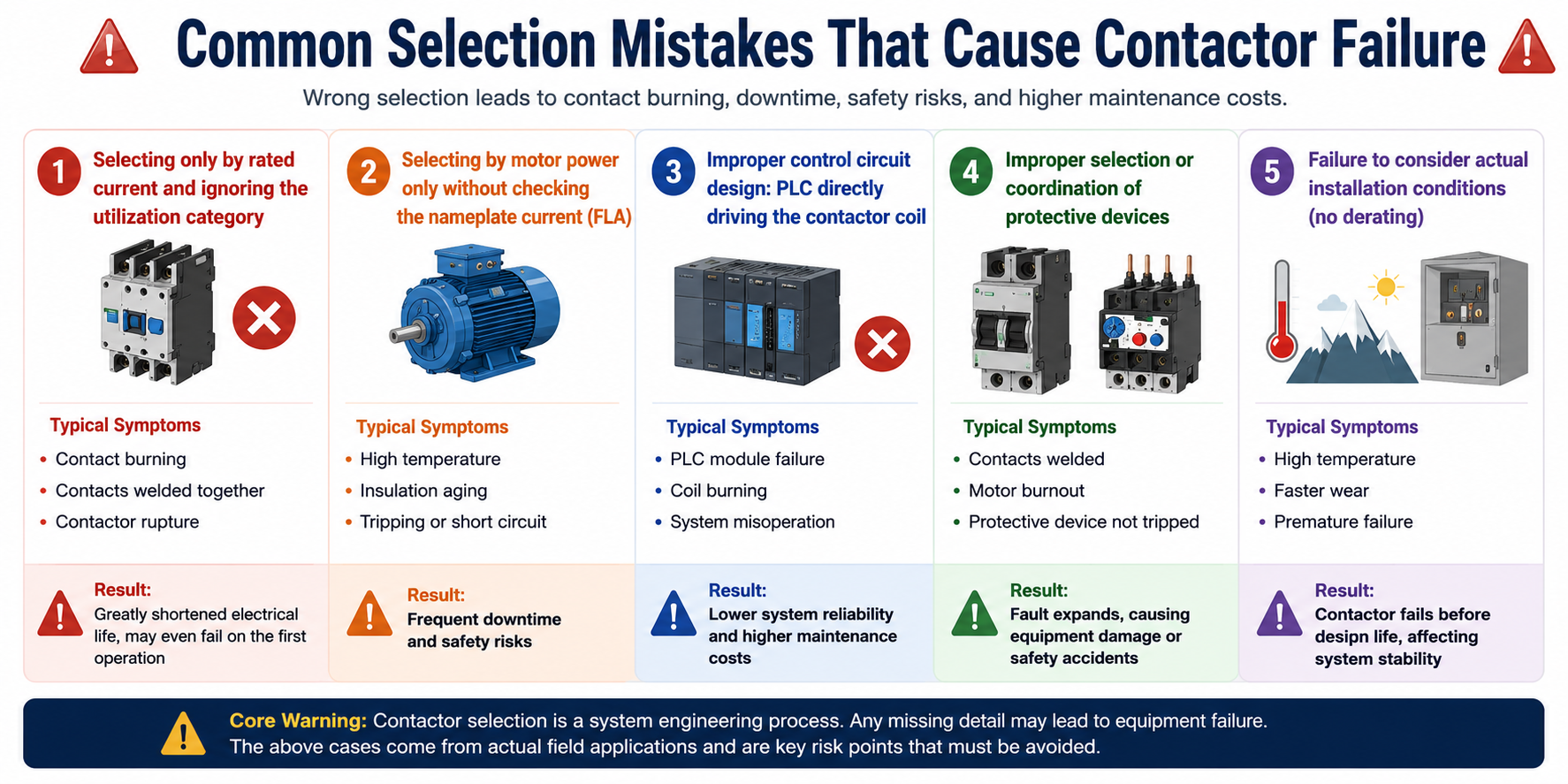
1. Selecting Only by Rated Current and Ignoring the Utilization Category
- Incorrect practice: Selecting directly according to the AC-1 or AC-3 current value on the nameplate, without choosing the corresponding utilization category based on the load type, such as motor, lighting, or capacitor loads.
- Failure symptoms:
- Using an AC-1 specification to control a motor: the starting inrush current may cause contact burning and contact welding.
- Using an AC-3 contactor to switch capacitors: the closing inrush current may cause contact welding or contactor rupture.
- Result: The electrical life of the contactor is greatly shortened, and it may even be damaged during the first closing operation.
2. Selecting by Motor Power Only Without Checking the Motor Nameplate Current
- Incorrect practice: Estimating the current only based on motor power in kW, without checking the motor nameplate full-load current (FLA).
- Failure symptoms: The contactor operates under overload for a long time, causing contact overheating, insulation aging, and eventually short circuits or tripping.
- Result: The equipment may stop frequently and create safety risks.
3. Improper Control Circuit Design: PLC Directly Driving the Contactor Coil
- Incorrect practice: Using the PLC transistor output to directly drive the contactor coil without using an interposing relay.
- Failure symptoms: The PLC output module may burn out due to the coil inrush current, the contactor coil may burn frequently, and the system may misoperate.
- Result: The reliability of the control system decreases, and maintenance costs increase.
4. Improper Selection or Coordination of Protective Devices
- Incorrect practice: The contactor is not used together with a circuit breaker or overload relay, or the protective coordination does not match, such as Type 1 / Type 2 coordination mismatch.
- Failure symptoms: During a short circuit, the contactor contacts may weld together and fail to open. During overload, the contactor may have no protection, causing the motor to burn out.
- Result: The fault expands, causing equipment damage or even safety accidents.
5. Failure to Consider Derating Under Actual Installation Conditions
- Incorrect practice: In high-temperature, high-altitude, or densely installed applications, the contactor is used without derating.
- Failure symptoms: The contactor temperature rise exceeds the limit, the contacts wear faster, and the contactor fails prematurely.
- Result: The contactor fails before its designed service life, affecting the stable operation of the system.
Core warning: Contactor selection is a system engineering process. Any missing detail may lead to equipment failure. The above cases all come from practical field applications and are key risk points that must be avoided during the selection process.
Conclusion
AC contactor selection is not simply about choosing a higher current rating. Reliable selection must start from the actual load and then match the utilization category, rated operational current, voltage, coil specification, auxiliary contacts, protective devices, and site conditions in sequence.
- For standard motor control, the AC-3 category and the motor nameplate full-load current should be used as the core selection basis.
- For frequent jogging / reversing, lighting, transformers, and capacitor circuits, selection must be based on dedicated categories such as AC-4, AC-5, and AC-6. Misuse of the utilization category can easily cause contact burning, contact welding, coil burnout, or even equipment damage.
A contactor cannot work alone. It must be properly coordinated with circuit breakers, overload relays, surge suppressors, PLCs, interposing relays, and other devices. In high-temperature, high-altitude, enclosed cabinet, dense installation, or high-frequency starting and stopping applications, derating must also be considered.
In short, contactor selection is a system-level decision. Correct selection can improve switching reliability, extend electrical life, reduce maintenance costs, and ensure that the entire electrical control system operates more safely and stably.
If you are not sure which contactor should be selected for your motor, lighting circuit, transformer, capacitor circuit, or control cabinet, you can contact our engineering team for selection support and technical consultation.
FAQs About AC Contactor Selection
Q1: What happens if I use an AC-1 rated contactor for an AC-3 motor load?
A: It will likely cause catastrophic premature failure or immediate welded contacts. AC-1 ratings are calibrated for purely resistive loads (like heaters) where the startup current equals the running current. An AC-3 motor draws 5 to 7 times its rated current during startup. Using an AC-1 contactor for an AC-3 application means the contacts are not engineered to handle or extinguish that massive inrush energy, leading to severe electrical arcing and micro-welding.
Q2: How do I choose between a 24VDC and a 230VAC control coil for my contactor?
A: This depends entirely on your system's control architecture and safety standards. 230VAC coils are highly common in traditional, standalone electrical panels because they don't require an extra power supply. However, for modern automated systems controlled by PLCs or smart controllers, 24VDC coils are the standard. 24VDC provides superior safety for maintenance personnel, isolates the control logic from high-voltage grid noise, and easily integrates with standard industrial power supplies.
Q3: When should I apply a derating factor to an AC contactor's nominal current?
A: You must apply a thermal derating factor in two main scenarios: high ambient temperatures and high altitudes. Contactors are typically rated for open-air environments up to 40°C. If the contactor is densely packed inside a sealed, non-ventilated Motor Control Center (MCC) enclosure where internal temperatures exceed 50°C, its current capacity drops. Additionally, if your project is located at an altitude above 2000 meters, the thinner air reduces both the cooling efficiency and the dielectric strength, requiring you to oversize the contactor frame.
-
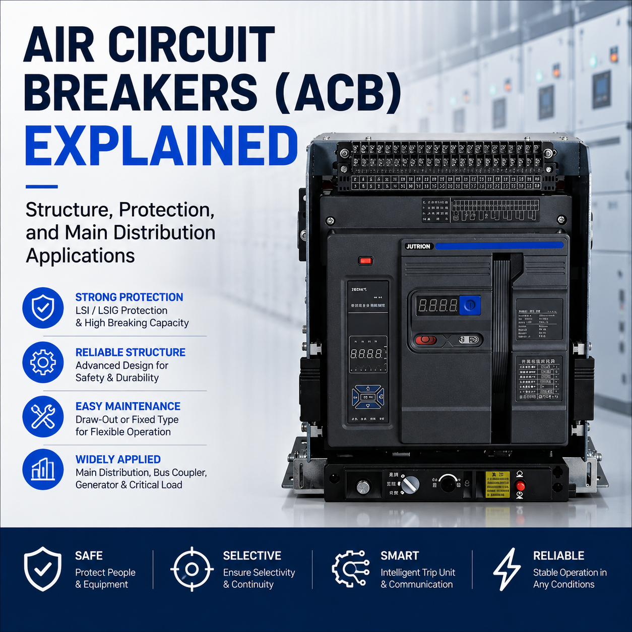
Air Circuit Breakers (ACB) Explained: Structure, Protection, and Main Distribution Applications
2026-05-24 22:21:27 -
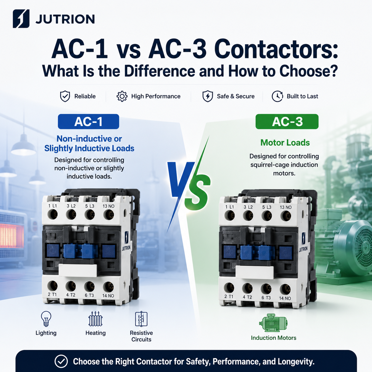
AC-1 vs AC-3 Contactors: What Is the Difference and How to Choose?
2026-05-20 19:31:24 -
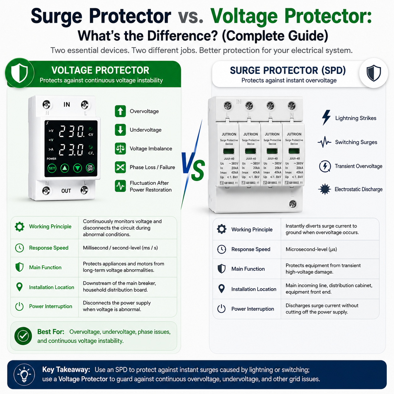
Surge Protector vs. Voltage Protector: What’s the Difference? (Complete Guide)
2026-05-18 17:50:53 -
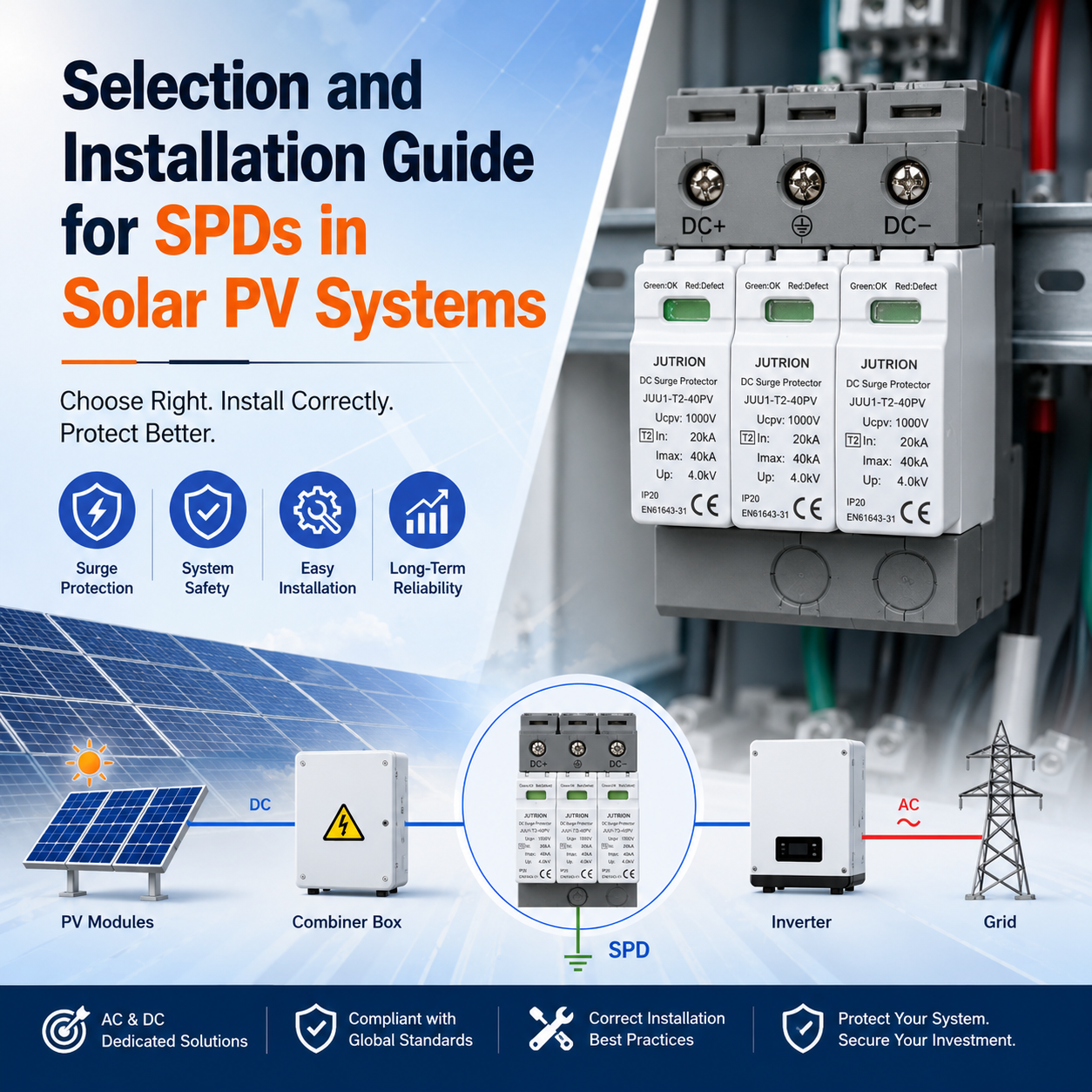
Selection and Installation Guide for SPDs in Solar PV Systems
2026-05-16 12:54:43 -
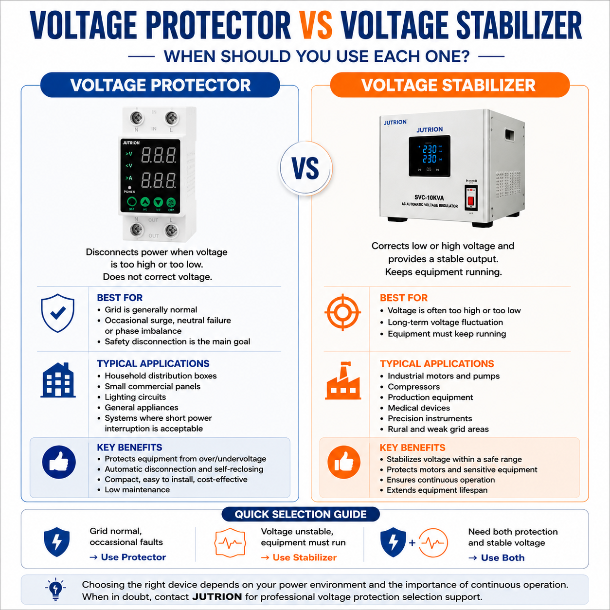
Voltage Stabilizer vs. Over and Under Voltage Protector: What Is the Difference?
2026-05-14 14:37:10