Type 2 surge protection devices are intended for installation in low-voltagepower distribution systems to control transient overvoltage caused by indirectlightning strikes and switching operations.The device is suitable for 230/400V AC systems at 50/60Hz and can be applied inTT, IT, TN-S, TN-C, and TN-C-S earthing arrangements. Performance is verifiedusing an 8/20µs impulse current waveform.Key electrical characteristics include nominal discharge current (In) andmaximum discharge current (Imax), defining the capability to repeatedly dischargesurge currents. The device is normally installed in distribution boards or downstream of a Type 1 device.Design and testing are carried out in accordance with IEC 61643-11 requirements.
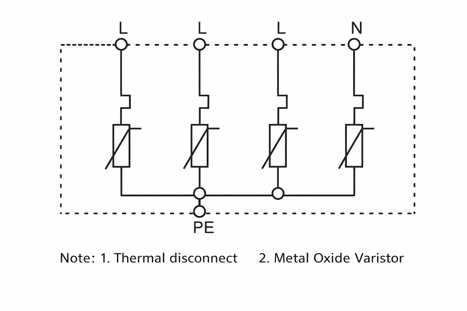
Main Structure and Working Principle:
In a three-phase four-wire system, three phase lines and one neutral line are each connected to a protective device to ground. Under normal conditions, the SPD is in a high-resistance state. When the power grid experiences lightning strikes or other causes of surge overvoltage, the SPD will immediately conduct within nanoseconds, guiding the surge overvoltage into the ground, thereby protecting the electrical equipment on the power grid. When the surge voltage passes through the SPD and disappears, the SPD returns to a high-resistance state, thus not affecting the normal operation of the power grid. The electrical principle diagram of the SPD is shown in the figure below.
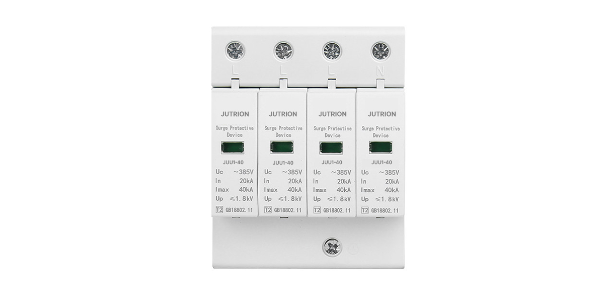
Main Technical Specifications (Example):
Rated Voltage (V): | 220V/380V |
Uc (V): | 385V |
Protection Class: | B/C/D |
Nominal Discharge Current In (8/20) (kA): | B:30 / 40 / 60 / 80 / 150 C:20 D:5/10 |
Maximum Discharge Current Imax (8/20) (kA): | B:60 / 80 / 100 / 150 / 200 C:40 D:10/20 |
Voltage Protection Level Up (kV): | B:2.2 / 2.4 / 2.5 / 3.5 / 3.5 C:2.0 D:1.2/1.8 |
Response Time (ns): | ≤ 25 |
Maximum Connection Cross-section (mm²): | 35 (rigid or flexible conductor) |
Recommended Wiring Cross-section (mm²): | 4 ~ 25 |
Recommended Circuit Breaker Rating: | 32A / 40–63A / 25A / 10A |
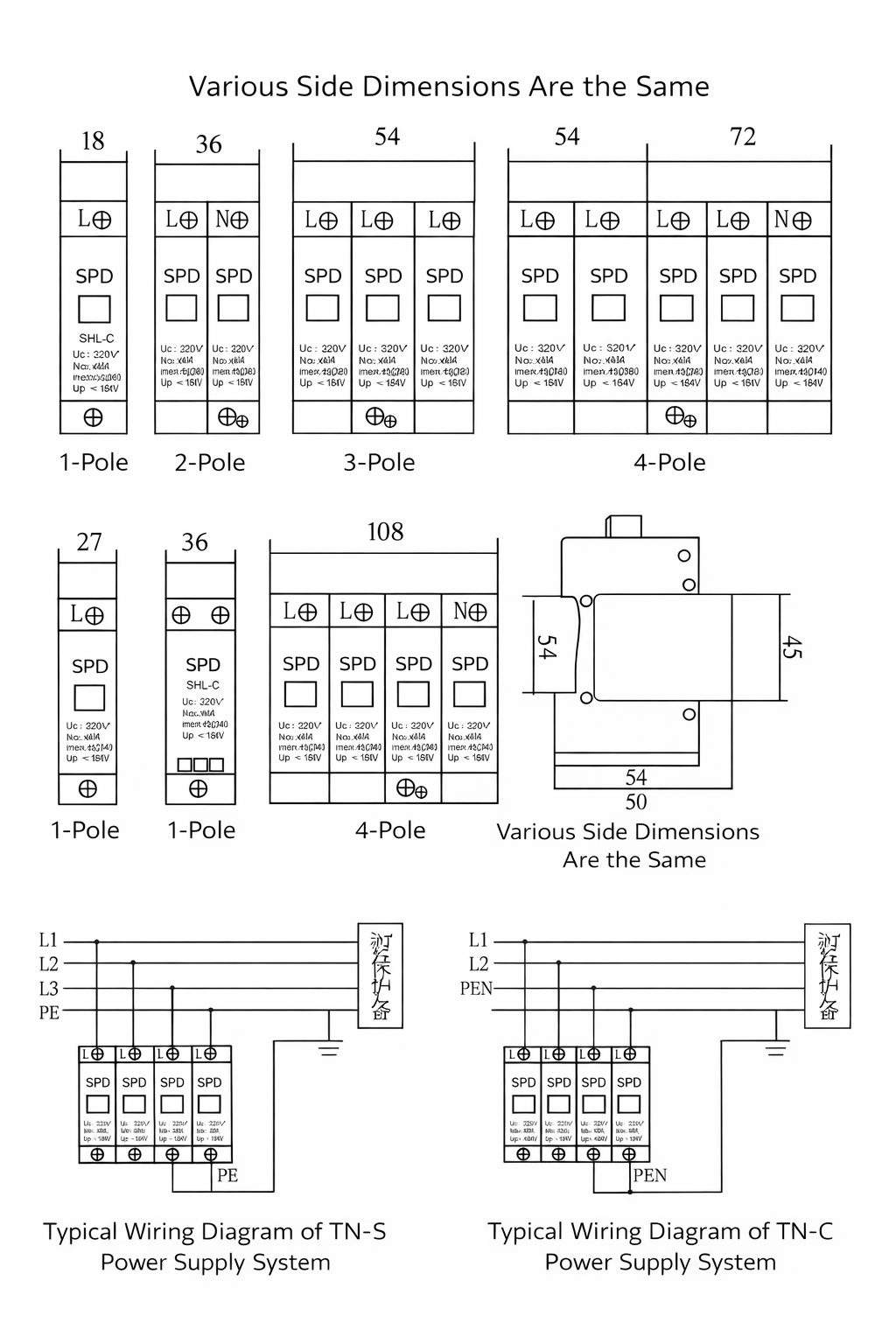
Wiring Diagram: